


6
PART IDENTIFICATION CHART
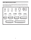
Use the drawings below to identify small parts used for assembly. The number in parentheses below each draw-
ing is the key number of the part, from the PART LIST near the end of this manual. The number following the key
number is the quantity used for assembly. Note: If a part is not in the hardware kit, check to see if it is preat-
tached. Extra parts may be included.
#8 x 3/4" Screw
(2)–10
1/4" Sta
Washer (14)–2
#8 x 1/2" Screw
3/8" Nut (12)–2
#10 x 3/4" Screw
(9)–2
#10 Star
Washer (12)–4
3/8" x 2 3/4" Screw (7)–4
5/16" x 1"
Bolt (4)–2
1/4" x 1" Patch
Bolt (9)–4
3/8" x 1 3/4" Bolt (6)–1
3/8" x 2" Bolt (3)–1
5/16" x 1"
Screw (5)–4
#8 x 1/2" Ground
Screw (10)–1
#8 x 1/2" Screw
(1)–16
5/16" x 1 1/4"
Bolt (4)–6
3/8" x 1 1/4"
Screw (8)–4
1/4" x 1/2"
Bolt (36)–4
1/4" Star
Washer (35)–4
#10 x 3/4" Flat
Head Screw (112)–2
1/4" Flat
Washer
(36)–2
1/4" Star
Washer
(35)–2
5/16" Flat
Washer
(113)–4
5/16" Star
Washer
(11)–8
3/8" Star
Washer
(13)–4