


12
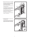
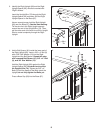
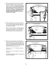
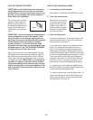
14. Attach the console assembly to the Right and
Left Handrails (104, 107) and the Crossbar (106)
with four #8 x 3/4" Screws (1) and four #8 x 1/2"
Screws (2). Start all eight Screws before tight-
ening any of them. Note: Use the two #8 x 1/2"
Screws that you removed in step 10.
Tighten the six 5/16" x 1" Bolts (6) (only three
are shown).
Tighten the two 1/4" x 3/4" Bolts (10) (only one
is shown).
See assembly steps 4 and 6. Firmly tighten the
four 3/8" x 4" Bolts (9).
2
104
107
Console Assembly
14
1
2
2
1
6
10
106
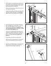
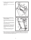
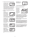
12. Have a second person hold the console assem-
bly near the Right Handrail (104) and the Left
Handrail (not shown). Connect the Upright Wire
(79) to the console wire. See the inset drawing.
T
he connectors should slide together easily
and snap into place. If they do not, turn one
connector and try again. IF THE CONNECTORS
ARE NOT CONNECTED PROPERLY, THE
C
ONSOLE MAY BE DAMAGED WHEN YOU
TURN ON THE POWER.
Console Assembly
12
Console
Wire
79
104
79
Console
Wire
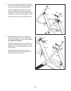
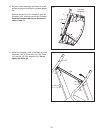
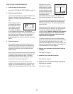
13. Attach the ground wire from the console assem-
bly to the Right Handrail (104) with a #8 x 1/2"
Ground Screw (3). Note: It may be difficult to
turn the Ground Screw.
Set the console assembly on the Right Handrail
(104) and the Left Handrail (107). Be careful
not to pinch the wires. Insert the connectors
and the excess wire into the Right Handrail.
Console Assembly
13
Ground
Wire
3
104
107