


10
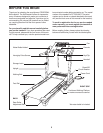
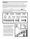
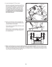
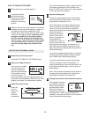
12. See the inset drawing. Push the Uprights (70,
76) sideways so that the treadmill Frame (26) is
centered between the Uprights.
Firmly tighten the Upright Bolts (84, 85) on each
side of the treadmill.
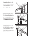
With the help of a second person, carefully raise
the Left Upright (70) and the Right Upright (76)
to a vertical position
76
70, 76
26
26
70
View From Above
Side View
12
85
84
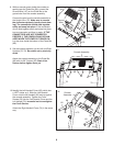
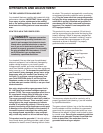
13. Make sure that all parts are properly tightened before you use the treadmill. If there are sheets of clear
plastic on the treadmill decals, remove the plastic. To protect the floor or carpet, place a mat under the tread-
mill. Note: Extra hardware may be included. Keep the included hex key in a secure place; the large hex key is
used to adjust the walking belt (see page 23).
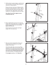
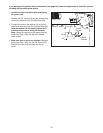
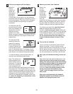
11.Lower the Uprights (70, 76) as shown.
S
tart the two indicated Console Screws (67) into
the Left and Right Uprights (70, 76) and the con-
s
ole assembly. If necessary, pull back on the
console assembly slightly to align the holes in
the Uprights with those on the console assem-
bly. Start the other two Console Screws be-
fore tightening all four; do not overtighten
the Console Screws.
Console Assembly
67
70
76
1
1
67
Start First
Start
First