


5
ASSEMBLY
Assembly requires two persons. Place all parts of the exercise cycle in a cleared area and remove the packing
materials. Do not dispose of the packing materials until assembly is completed.
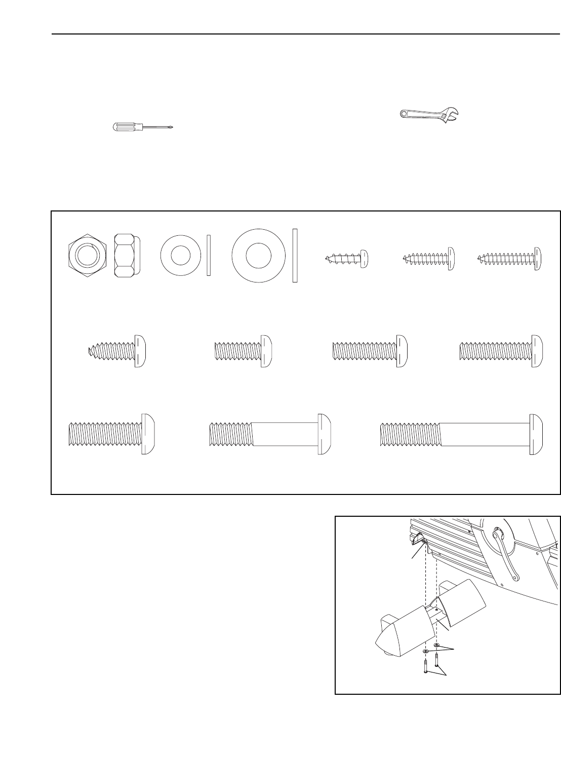
Assembly requires the included tools and your own adjustable wrench and Phillips
screwdriver .
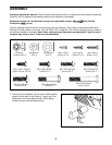
Use the drawings below to identify the small parts used for assembly. The number in parenthesis below each
drawing is the key number of the part, from the PART LIST on page 25. The number following the key number is
the quantity needed for assembly. Note: Some small parts may have been pre-assembled. If a part is not in
the parts bag, check to see if it has been pre-assembled.
M8 x 52mm Button
Screw (54)–2
M6 x 16mm Button
Screw (8)–4
M4 x 12mm
Screw (41)–4
M8 Nylon
Locknut (49)–4
M8 Washer
(64)–2
M6 Washer
(66)–4
M8 x 25mm Button
Screw (40)–4
M6 x 22mm Button
Screw (93)–3
M8 x 38mm Button
Bolt (96)–4
M6 x 16mm Tapered
Button Screw (102)–8
M4 x 20mm
Screw (101)–1
M4 x 16mm
Screw (57)–10
M6 x 25mm Button
Screw (99)–1
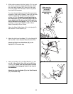
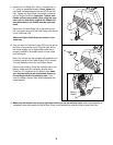
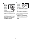
1. Orient the Front Stabilizer (15) as shown. While another
person lifts the front of the Frame (1), attach the Front
Stabilizer to the Frame with two M8 x 52mm Button
Screws (54) and two M8 Washers (64).
15
54
64
1
1