


8
47
42
44
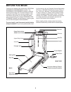
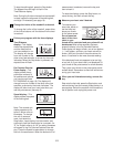
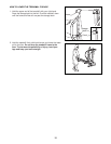
7. Insert the excess Wire Harness (42) into the large hole in
the side of the Right Handrail (72). Securely tighten the
plastic ties on the bottom of the Console Base (47) to
prevent the Wire Harness from slipping. Then, cut off
the ends of the plastic ties.
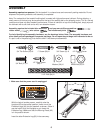
Route the Wire Harness (42) through the indicated open-
ing in the Console Base (47). Attach the Wire Cover to the
Console Base (47) with a 1/2” Silver Screw (48).
Note: Do
not overtighten the 1/2” Silver Screw.
Attach the Console Base (47) to the Crossbar (40) with two
3/4” Screws (2). Tighten the two Crossbar Screws (39)
(only one Crossbar Screw is shown).
7
2
72
48
40
Ties
47
Ties
72
6
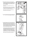
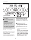
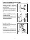
6. Loosen the two Crossbar Screws (39) two turns (only one
Crossbar Screw is shown). Place the Console Base (47) on
the Right Handrail (72) and the Left Handrail (not shown).
Attach the Console Base with four 3/4” Screws (2) (only two
Screws are shown).
Do not overtighten the Screws.
Insert the Wire Harness (42) through the two indicated plas-
tic ties on the Console Base (47). Next, touch the Right
Handrail (72) to discharge any static. See the inset draw-
ing. Find the 5-pin connector on the end of the Wire
Harness. Insert the connector into the red socket beneath
the console.
The connector should slide easily into the
socket and snap into place. If the connector does not
slide easily and snap into place, turn the connector and then
insert it. Insert the 6-pin connector into the black socket be-
neath the console in the same way.
Make sure that the connectors and wires appear as
shown in the inset drawing.
IF THE CONNECTORS ARE
NOT INSERTED PROPERLY, THE CONSOLE MAY BE
DAMAGED WHEN THE POWER IS TURNED ON.
42
43
2
Opening
6-pin
42
5-pin
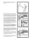
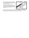
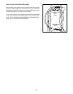
5. Attach the end of the ground wire to the small hole in the
side of the Right Handrail (72) with a Silver Ground
Screw (75).
Ground
Wire
72
75
5
39
39