


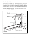
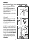
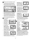
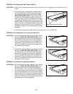

1. With the help of a second person, carefully lay the
treadmill on its right side.
Insert an Extension Leg (103) into the base of the left
Upright (82) as shown. Make sure that the Extension
Leg is turned so the Warning Decal (20) is on the side
shown. Tighten two of the four Short Screws (101) into
the left Upright and the Extension Leg. Attach the other
Extension Leg in the same way.
With the help of a second person, carefully raise the
treadmill to the vertical position so that both Extension
Legs (103) are resting flat on the floor.
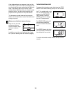
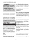
3. Cut the plastic tie off the bracket on the base of each
Upright (82). Next, cut the plastic tie off the Left Handrail
(74). Position the Left Handrail on the left Upright (82).
The bracket on the base of the left Upright should be in-
side of the lower end of the Left Handrail, as shown in
inset drawing C.
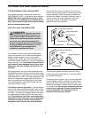
Refer to inset drawing A. While a second person holds
the Right Handrail (85) and the Console (not shown) near
the right Upright (82), cut the indicated plastic ties off the
Right Handrail. Do not cut the other plastic tie in the
Right Handrail. Next, cut the plastic tie off the Upright
Wire Harness (34) in the right Upright (82). Do not drop
the Upright Wire Harness into the right Upright.
Refer to inset drawing B. Connect the Console Wire
Harness (48) to the Upright Wire Harness (34). The latch
on the Console Wire Harness should snap onto the
Upright Wire Harness. If the Wire Harnesses do not fit
together easily, turn them; do not force the Wire
Harnesses together.
20
82
101
103
1
Plastic Tie
74
82
Plastic
Tie
3
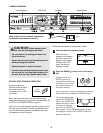
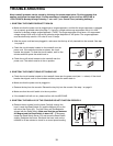
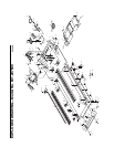
2. Refer to HOW TO LOWER THE TREADMILL FOR
USE on page 11. Follow the instructions in step 2 to
lower the treadmill.
Without removing the tape from the Latch (77), attach
the Latch to the left Upright (82) with two 3/4Ó Screws
(81). Make sure that the Screws are tight, but do not
overtighten them; if the Screws are overtightened,
the Latch will not slide smoothly. After the Latch is
attached, remove any visible tape.
Note: The inset drawing shows how the parts of the
Latch (77) fit together.
77
81
82
2
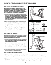
ASSEMBLY
Assembly requires two people. Set the treadmill in a cleared area and remove all packing materials. Do not
dispose of the packing materials until assembly is completed. Assembly requires the included allen wrench
and your own phillips screwdriver , adjustable wrench and scissors .
Spacer
Springs
Bracket
77
48
34
Plastic
Ties
A
B
34
48
85
82
Do not
cut
Bracket
74
C
5