


8
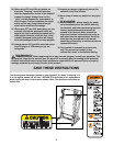
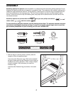
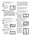
6. Make sure that all parts are properly tightened before you use the treadmill. Note: Extra hardware may
be included. Keep the included allen wrenches in a secure place. The large allen wrench is used to adjust the
walking belt (see page 27). To protect the floor or carpet, place a mat under the treadmill.
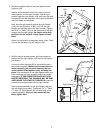
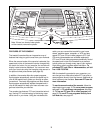
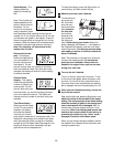
5. Remove the knob from the pin. Make sure that the collar
and the spring are on the pin as shown. Insert the pin
into the Latch Housing (75) and tighten the knob back
onto the pin.
Raise the Frame (54) to the vertical position. While an-
other person holds the Frame, hold the Latch Housing
(75) against the inside of the Frame. Thread two 3/4”
Screws (6) several turns into the Latch Housing and the
Frame.
Align the pin with the hole in the Left Handgrip (76) by
sliding the Latch Housing (75) up or down. Make sure
that the pin can be inserted fully into the hole. Hold
the Latch Housing in place and tighten the two 3/4”
Screws (6). Be careful not to overtighten the Screws.
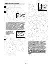
Pull the knob to the right and carefully lower the Frame
(54) to the floor. Press the Latch Cover (12) into the left
side of the Frame. See the inset drawing. Make sure that
the notch in the Latch Cover is positioned over the Foot
Rail (2) as shown.
Note: Over a period of use, the Latch Housing (75) may
need to be adjusted again to align the pin with the hole in
the Left Handgrip (76).
54
Spring
Knob
Collar
Pin
75
76
Hole
12
5
6
12
2
Notch
54
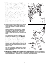
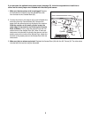
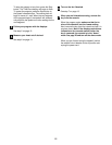
4. With the help of a second person, carefully tip the
Uprights (109) down to the position shown. Make sure
that the Extension Legs (128) remain in the Uprights.
Press the two Base Endcaps (99) into the base of the
Uprights (109). See the inset drawing. Make sure that
the angle of each Endcap matches the angle of the
Upright.
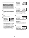
Attach each Extension Leg (128) with two 3/4” Tek
Screws (47) and a Round Base Pad (67) as shown.
(Note: Attach the lower Screw [without the Round Base
Pad] first.) Attach the two Base Pads (100) with four 3/4”
Tek Screws. Note: There are no screw holes in the Base
Endcaps (99). Press firmly on the screwdriver when
tightening the 3/4” Tek Screws (47).
With the help of a second person, carefully raise the
Uprights (109) so the Base Pads (100) are resting on the
floor.
109
128
128
67
100
67
47
47
47
4
99
99
99
109
100
47