


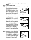
6. Make sure that all parts are tightened before you use the treadmill. Keep the included allen wrench in a
secure place. The allen wrench is used to adjust the walking belt (see page 13). To protect the floor, place a
mat under the treadmill.
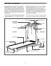
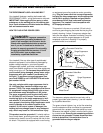
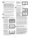
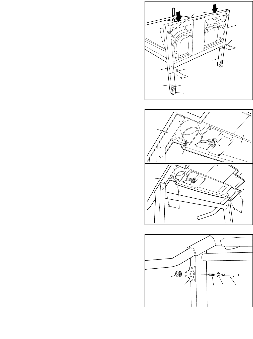
4. Place the Console Base (87) on the Handrails (85, 23).
Make a loop with the indicated plastic tie and insert the
two Wires (17) through the loop. Pull out just enough of
the two Wires to connect them to the connectors in the
Console Base, and then plug the Wires into the connec-
tors. Important: Make sure that the Wires are fully in-
serted. Tighten the loop and cut off the excess plastic tie.
WARNING: Do not disconnect or connect the Wires
while the treadmill power cord is plugged in.
Refer to drawing 4b. Thread four Long Screws (79) into the
Handrails (85, 23) and the Console Base (87). After all four
Long Screws have been started, tighten the Screws
until they are snug; do not overtighten the Screws.
Refer to drawing 2c. Tighten the four Handrail Bolts (89).
79
79
85
85
Tie
87
23
87
4a
4b
3
101
101
82
103
103
82
97
95
97
52
52
97
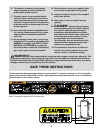
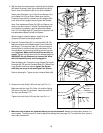
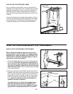
3. With the help of a second person, carefully tip the Uprights
(82) down as shown. Note: It may be helpful to place a
foot on one of the Wheels (95) as you tip the treadmill.
Attach each Extension Leg (103) with two Screws (101)
and a Base Pad (52) as shown. Make sure that the
Extension Legs are fully inserted into the Uprights (82);
push down on the Uprights as you tighten the Screws.
Note: One replacement Base Pad (52) and Spacer (not
shown) may be included. If a Base Pad becomes worn
and needs to be replaced, use the replacement Base
Pad. If a Thick Base Pad (97) needs to be replaced, use
the replacement Base Pad with the Spacer.
With the help of a second person, carefully tip the
Uprights (82) back to the upright position.
6
17
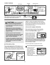
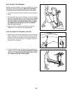
5. Remove the Lock Knob (105) from the Lock Pin (11).
Make sure that the Lock Pin Collar (14) and the Spring
(56) are on the Lock Pin as shown. Insert the Lock Pin
into the Latch Bracket (77).
Tighten the Lock Knob (105) onto the Lock Pin (11).
14
56
11
77
105
5