


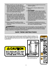

11.Make sure that all parts are properly tightened before you use the treadmill. Note: There may be hard-
ware left over after assembly is completed. Keep the included allen wrench in a secure place; the allen wrench
is used to adjust the walking belt (see page 25). To protect the floor or carpet from damage, place a mat
under the treadmill.
8
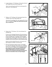
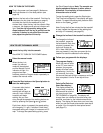
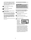
8. Attach the matching Left Bottom Handgrip (82) with three
1/2” Screws (33).
Attach the Right Top Handgrip and the Right Bottom
Handgrip (not shown) as described above.
33
82
9
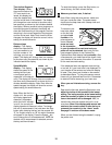
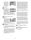
9. Attach a Wheel (58) to the right side of the Base (116)
with a Wheel Bolt (56) and a Nut (3) as shown.
Attach a Wheel to the left side of the Base (not shown) in
the same way.
58
56
3
116
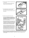
10
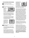
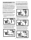
10. Carefully lower the Uprights (55, 64) as shown.
Press the Console Back (40) onto the back of the
Console Base (38). Make sure that Console Back and
Console Base are mated correctly and that no wires
are pinched. Tighten two 1/2” Silver Screws (114) into
the indicated holes. Tighten 3/4” Screws (37) into the
other holes in the Console Back.
Make sure that the left side of the Left Upright (64) is flush
with the left side of the Base (116). Firmly tighten, but do
not overtighten, the two Upright Bolts (112) in the left side
of the Base. Then, make sure that the Right Upright (55)
is flush with the right side of the Base. Tighten the two
Upright Bolts (not shown) in the right side of the Base.
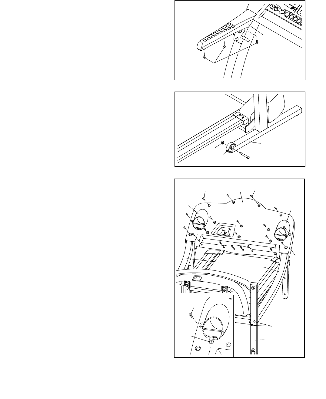
Insert the Left and Right Cup Holders (39, 50) into the
large holes in the Console Base (38). If there is a small
hole under each Cup Holder, the two Small Clamps (117)
should be attached. Refer to the inset drawing. Loop a
Small Clamp through the hole in the bottom of a Cup
Holder and attach it with a 3/4” Screw (37). Attach a Small
Clamp to the other Cup Holder in the same manner.
Raise the Uprights (55, 64) back to the vertical position.
40
39
50
38
37
114
114
112
64
55
116
8
37
117