


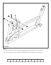
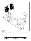

11−1/4"
6
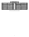
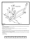
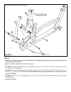
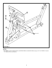
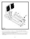
FIGURE 2
STEP 2:
• SECURELY assemble the SECOND ARM (5) to the FRAME (1) using one 1/2 X 4-3/4” BOLT (12), one 3/4 X 4” SHAFT (15) and one
1/2” LOCK NUT (13). See FIGURE 2.
• SECURELY assemble the MAIN ARM (4) to the FRAME (1) using one 1/2 X 4-3/4” BOLT (12), one 3/4 X 4” SHAFT (15) and one 1/2”
LOCK NUT (13). See FIGURE 2. (NOTE: Make sure MAIN ARM is orientated correctly, top hole should be 11-1/4” from the top of arm
as shown in FIGURE 2.)
• NOTE: Follow STEP 2 for the assembly of the LEG PRESS to the CM3 and GS6 Gym System. If you have the GS1, GS2, GS4 or GS8
Gym Systems proceed to STEP 3.
• Proceed to to STEP 3.
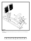
• SECURELY assemble two 1-1/2 X 2 BUMPERS (16) to each side of the MAIN ARM (4) where the MAIN ARM (4) contacts the FRAME
(1) See FIGURE 2.
12 1/2 X 4-3/4”
1
13
15
4
5
16
For assembly to the CM3 and GS6 Gym System .
Make sure MAIN ARM
is orientated correctly
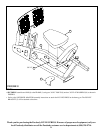
• NOTE: FLANGE BEARINGS SHOULD BE PRE-INSTALLED