7
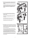
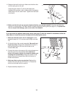
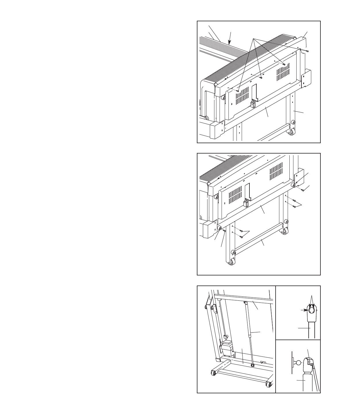
2. With the help of a second person, carefully tip the Frame
(55) and the Uprights (85) down to the position shown.
Make sure that the Base Extension (90) remains in the
Uprights.
Carefully slide the Base Cover (92) onto the bottom of the
Uprights (85). Attach the Base Cover with four 3/4” Tek
Screws (44); start all four Tek Screws before tighten-
ing them. Be careful not to overtighten the Tek
Screws.
92
90
44
55
85
2
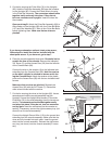
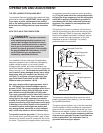
3. Attach the Base Extension (90) with four Extension
Screws (87);
start all four Extension Screws before
tightening them.
Attach the two Thin Base Pads (83) to the base of the
Uprights (85) in the locations shown with two 1” Tek
Screws (82).
Note: Replacement Base Pads may be included. Use the
Base Pads to replace any that becomes worn.
With the help of a second person, carefully tip the
Uprights (85) back to the vertical position.
87
85
83
82
87
90
83
82
3
4.
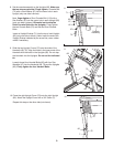
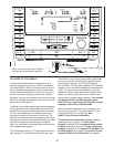
See drawing 4a. Look into the openings in the ends of the
Shock (86), and make sure that the ends of the metal clips
are centered as shown. If necessary, rotate the metal clips
slightly. Twist the ends of the Shock, if necessary, to align
the openings with the brackets on the Frame (55) and the
base of the Uprights (85).
While the other person holds the Frame (55), press the
smaller end of the Shock (86) onto the bracket in the cen
-
ter of the Uprights (85). See drawing 4b. It may be helpful
to use a flat head screwdriver to lift each metal clip
slightly.
Do not remove the metal clips. Make sure to
orient the Shock as shown. Press the other end of the
Shock onto the bracket in the center of the Frame. Note: It
may be necessary to tip the Frame forward or back to at
-
tach the Shock. Do not tip the Frame forward past the
vertical position.
85
4
86
55
Metal Clip
Metal Clip
86
86
Opening
4a
4b


