


MAINTENANCE AND TROUBLESHOOTING
Inspect and tighten all parts of the elliptical exerciser
regularly. Replace any worn parts immediately.
To clean the elliptical exerciser, use a damp cloth and
a small amount of mild soap. Important: To avoid
damage to the console, keep liquids away from
the console and keep the console out of direct
sunlight.
BATTERY REPLACEMENT
If the console displays become dim, the batteries
should be replaced; most console problems are the
result of low batteries. See assembly step 9 on page
8 for replacement instructions.
HANDGRIP PULSE SENSOR TROUBLESHOOTING
If the handgrip pulse sensor does not function proper-
ly, see step 5 on page 15.
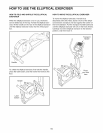
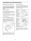
HOW TO ELIMINATE RUBBING OF THE DISCS
If the Discs (12) rub against the Side Shields (14, 15)
during use, make sure that the Center Foot (40) is
installed in the Frame (1). tf the Center Foot is
installed, loosen the two indicated Bolt Sets (88) and
the two M4 x 16mm Screws (78) in each side of the
elliptical exerciser.
88
14, 15
78
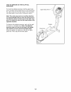
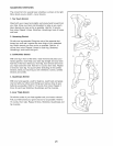
HOW TO ADJUST THE BELT
If the pedals slip while you are pedaling, even while
the resistance is adjusted to the highest setting, the
belt may need to be adjusted. To adjust the belt, first
see assembly step 12 on page 10 and remove the left
pedal arm and the left link arm.
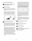
Then, carefully
pry off the left
Disc Cover (13)
using a flat
screwdriver.
Next, remove the
four screws (not
shown) from the
center of the left 13
Disc (12). Gently 12
rotate the Disc
Cover and the
Disc away from the elliptical exerciser.
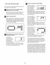
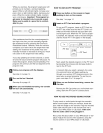
Loosen, but do
not remove, the
three indicated
screws (A). Insert
the shaft of a
screwdriver
downward
between the
Idler (47) and the
Idler Pulley (48).
Pull the top of the
screwdriver
toward the front
of the elliptical exerciser until the Belt (74) is tight.
Then, tighten the three screws.
Reattach the left disc with the four screws and then
reattach the left disc cover. Next, see assembly step
12 on page 10 and reattach the left pedal arm and the
left link arm.
Adjust the position of the Side Shields (14, 15) until
the Discs (12) no longer rub against them, and then
tighten the Bolt Sets (88) and the M4 x 16mm Screws
(78).
19