


7
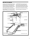
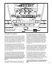
6. Make sure that all parts are tightened before you use the treadmill. Note: If there is a thin sheet of clear
plastic on the face of the hood decal and the “ComforTrack” decal, remove it. Keep the included allen wrench in
a secure place. The allen wrench is used to adjust the walking belt (see page 27). To protect the floor or car-
pet from damage, place a mat under the treadmill.
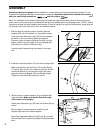
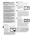
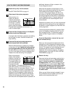
5. Insert two Handrail Bushings (75) into the right Upright
(69). Turn the Handrail Bushings so they fit against the
Upright with the thick sides of the Bushings facing the
center of the treadmill as shown in the inset drawing.
Insert two Handrail Bolts (78) with Handrail Washers
(77) into the Handrail Bushings (75), the right Upright
(69), and the right Handrail Spacer (65). Lift the right
Handrail (66) to align the Bolts with the holes in the
Handrail. Next, thread the Bolts into the Handrail. Do
not tighten the Bolts yet.
Attach the left Handrail (not shown) in the same way.
Tighten all four Handrail Bolts (78).
5
78
77
75
69
66
65
75
77
Thick
Side
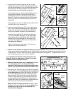
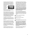
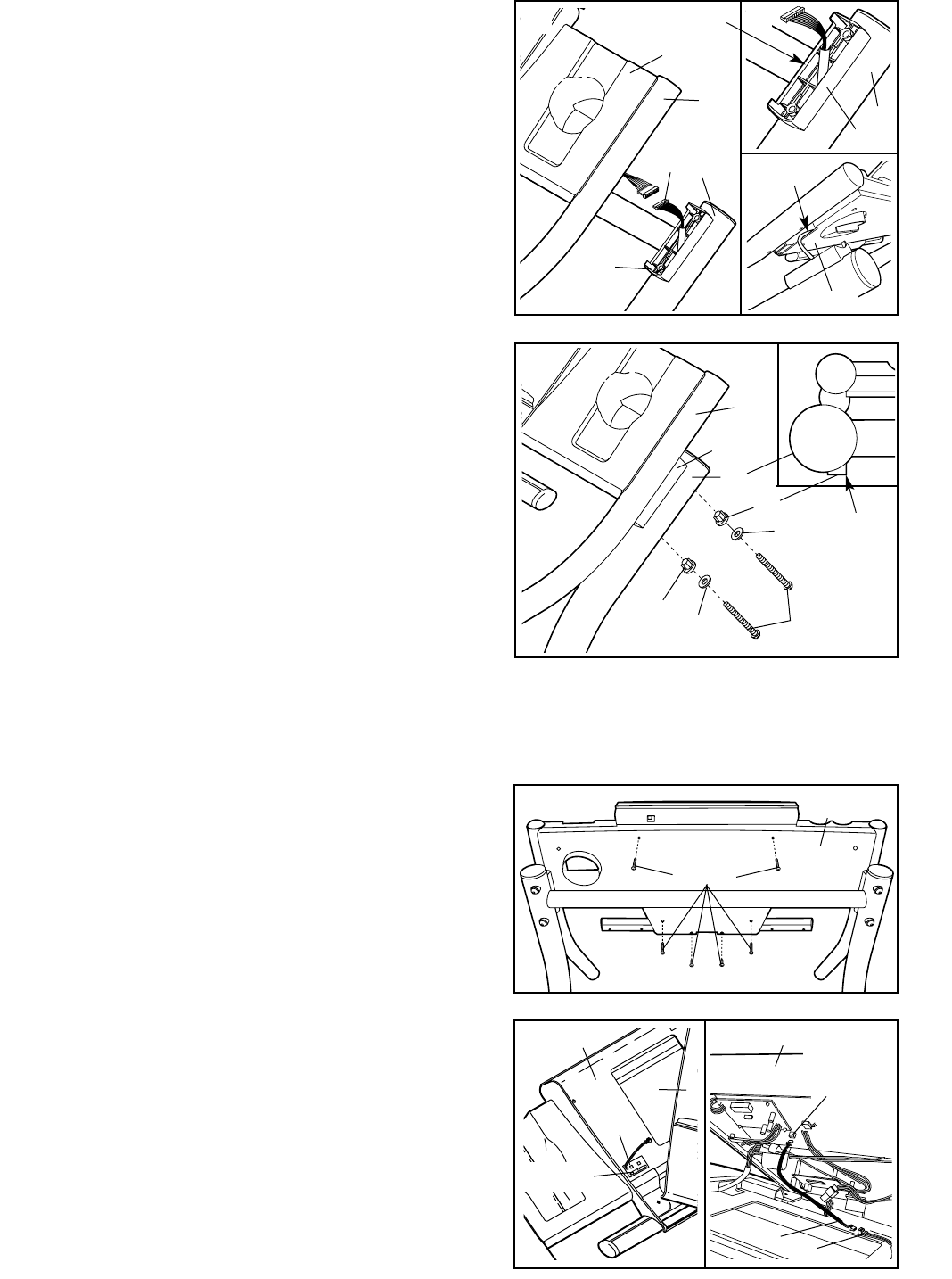
4. Place one of the Handrail Spacers (65) on the right
Upright (69) as shown, with the cutout toward the tread-
mill (see inset drawing A). Pull the Upright Wire Harness
(98) up through the Handrail Spacer. Place the other
Handrail Spacer on the left Upright (not shown).
Have a second person hold the Handrails (66) near the
Uprights (69) as shown. Connect the Upright Wire
Harness (98) to the wires extending from the Console
Base (81). Insert the connectors and the Wire Harness
(98) into the hole in the Console Base (81) (see inset
drawing B).
Being careful not to pinch the Wire Harness (98), set the
Handrails (66) on the Spacers (65).
4
98
69
66
81
65
69
65
81
98
A
B
Cutout
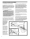
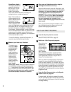
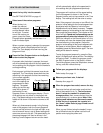
If you purchase the optional chest pulse sensor (see
page 24), follow the steps below to install the receiver
included with the chest pulse sensor.
1. Make sure that the power cord is unplugged. Remove
the indicated Screws from the Console Back (88).
Important: The Screws may be different lengths. Keep
track of which Screws were removed from which holes.
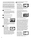
2. See drawing 2a. Peel the paper off the pad on the bottom
of the Receiver (A). Turn the Receiver so the cylinder is
on the side shown, and press the Receiver into the bot-
tom of the Console Base (81) in the indicated location.
See drawing 2b. Connect the Short Jumper Wire (B) to
the wire on the Receiver (A). Connect the other end of
the Jumper Wire to the PULSE jack on the back of the
Console (82). Note: The included Long Jumper Wire and
Wire Tie are not needed and can be discarded.
Make sure that no wires are pinched. See step 1 above.
Reattach the Console (82) with the Screws. Note: If the
Screws are not put in the correct locations, the
Console will be damaged.
2b
Screws
2a
82
82
88
81
A
B
A
Cylinder
PULSE
Jack