


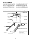
7. Make sure that all parts are tightened before you use the treadmill. Note: If there is a thin sheet of clear
plastic on the hood decal, remove it. Keep the included allen wrench in a secure place. The allen wrench is
used to adjust the walking belt (see page 24). To protect the floor or carpet from damage, place a mat under
the treadmill.
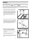
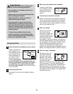
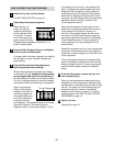
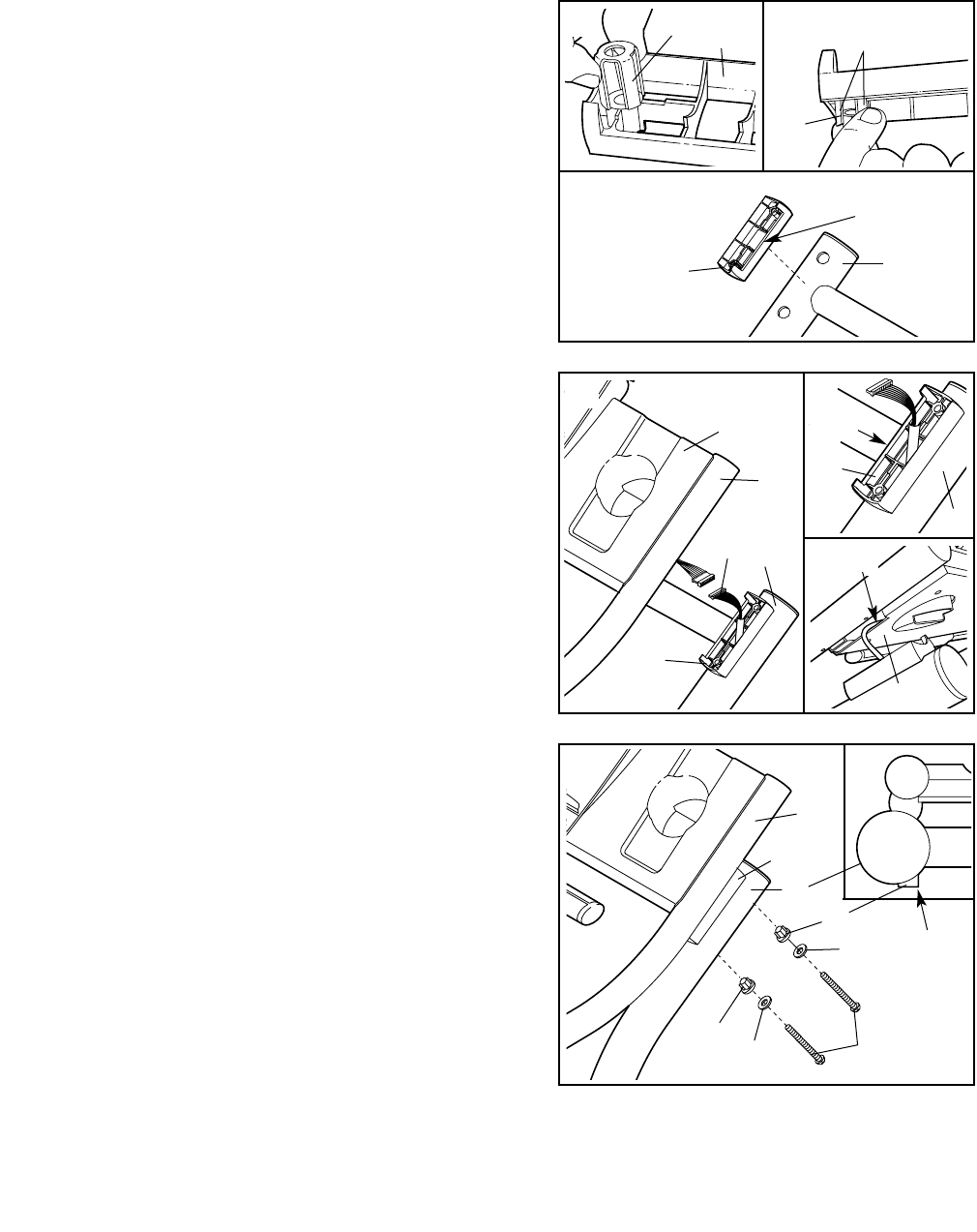
6. Insert two Handrail Bolts (78) with Handrail Washers
(77) and Handrail Bushings (75) into the right Upright
(69) and the right Handrail Spacer (65). Turn the
Handrail Bushings so they fit against the Upright with
the thick sides of the Bushings toward the center of the
treadmill as shown in the inset drawing. Lift the right
Handrail (66) slightly and align the Bolts with the holes
in the Handrail. Next, thread the Bolts into the Handrail.
Do not tighten the Bolts yet.
Attach the left Handrail (not shown) in the same way.
Tighten all four Handrail Bolts (78).
6
78
77
75
Thick
Side
69
66
65
75
77
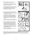
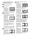
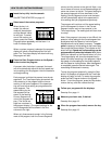
5. Pull the Upright Wire Harness (98) up through the other
Handrail Spacer (65). Place the Handrail Spacer on the
right Upright (69) as shown, with the cutout turned toward
the treadmill (see inset drawing A).
Have a second person hold the Handrails (66) near the
Uprights (69) as shown. Connect the Upright Wire
Harness (98) to the wires extending from the Console
Base (81). Insert the connectors and the Upright Wire
Harness into the hole in the Console Base (see inset
drawing B).
Set the Handrails (66) on the Handrail Spacers (65),
being careful not to pinch the Upright Wire Harness (98).
5
98
69
66
81
65
69
65
81
98
A
B
7
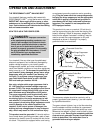
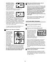
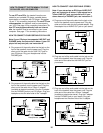
4. Slide the Grounding Bracket (107) onto one of the
Handrail Spacers (65) in the location shown.
See inset drawing A. Pinch the tabs on the Grounding
Bracket (107) so that the tabs will fit into the hole in the
Upright (69 [see inset drawing B]).
See inset drawing B. Place the Handrail Spacer (65) on
the left Upright (69) as shown, with the cutout on the indi-
cated side. Note: Make sure that the tabs on the
Grounding Bracket (107 [see inset drawing B]) are in-
serted into the hole in the Upright.
4
Tabs
A
B
69
107
107
65
65
Cutout
Cutout