


5
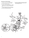
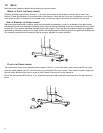
ASSEMBLING THE CROSS-TRAINER
Tools required: Metric Socket set, Phillips
Screwdriver, Metric Wrench set
1. Position the base unit near the desired location for use
(Refer to the "Getting Started" section of this manual for
proper location). Locate and install the four LEVELER FEET
(A) into the front and rear STABILIZERS as shown.
2. With the DISPLAY CONSOLE MOUNTING PLATE (B) facing
upward, lay the UPRIGHT TUBE ASSEMBLY (C) on floor in
front of BASE FRAME (D). Cut the wire tie securing the
LOWER WIRE HARNESS (E) to the front of the BASE
FRAME. Connect the UPPER WIRE HARNESS (F) to the
LOWER WIRE HARNESS.
3. Position the UPRIGHT TUBE ASSEMBLY (C) between the
plates on the front of the BASE FRAME (D). Feed any
excess wire harness into the BASE FRAME. Tilt the
UPRIGHT TUBE ASSEMBLY into an upright position. Align
the holes on the plates with the holes on the UPRIGHT
TUBE ASSEMBLY. Secure the UPRIGHT TUBE ASSEMBLY
to the BASE FRAME using four 2-3/4" BOLTS (1), eight CAP
WASHERS (2) (4 on each side) and four NUTS (3). Tighten
until snug.
4. Using two 1" BOLTS (4), secure the UPRIGHT TUBE
ASSEMBLY (C) to the backside of the connector joint on the
BASE FRAME (D). Tighten all the BOLTS securely. Install
eight black PLASTIC COVER CAPS (5) over each 2-3/4"
BOLT HEAD (1 & 4) and NUT (3).
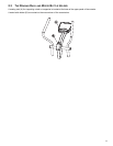
5. Slide the tab of the UPRIGHT TUBE ANGLE BRACE (G)
into the slot located near the base of the UPRIGHT TUBE
ASSEMBLY (C) and pivot the UPRIGHT TUBE ANGLE
BRACE downward to met the BASE FRAME (D). Using two
screws (6) secure the UPRIGHT TUBE ANGLE BRACE to
the UPRIGHT TUBE ASSEMBLY and BASE FRAME as
shown.
6. Slide one LARGE FLAT WASHER (7) and one LARGE
WAVE WASHER (8) onto the user right PIVOT SHAFT (H).
Slide the WASHERS fully over the PIVOT SHAFT until seat-
ed against the pre-installed STOP RING.
7. Locate the user right ROCKER ARM ASSEMBLY (J)
(Marked with an “R”). With the top handgrip facing the front
of the unit (as shown), slide the user right ROCKER ARM
ASSEMBLY onto the user right PIVOT SHAFT (H) until seat-
ed against the WASHERS (7 & 8). Secure the ROCKER
ARM ASSEMBLY to the PIVOT SHAFT using one FLAT
WASHER (9), LOCK WASHER (10), and 1-1/4” HEX BOLT
(11). Tighten the BOLT securely. Insert one ROCKER ARM
END CAP (12) into the end of the ROCKER ARM SHAFT.
Repeat the procedure for the user left ROCKER ARM
ASSEMBLY (K).
8. Locate the user right PEDAL LEVER (L) and PEDAL (M).
Position the PEDAL above the PEDAL MOUNTING PLATE
(N) and secure the PEDAL using four SCREWS (13) and
LOCK WASHERS (14). Tighten the SCREWS securely.
Repeat for the user left PEDAL (O) and PEDAL LEVER (P).
9. Position the rear end of the user right PEDAL LEVER (L)
near the user right REAR CLEVIS (Q). Position the end of
the PEDAL LEVER between the clevis flanges. Align the
holes and secure as shown using two CAP WASHERS (2),
one 3 1/4" BOLT (15), one NUT (16) and two PLASTIC
COVER CAPS (5). Tighten the BOLT and NUT securely.
10. Lift the front end of the user right PEDAL LEVER (L) to meet
the user right ROCKER ARM CLEVIS (R). Secure the
PEDAL LEVER to the ROCKER ARM CLEVIS using two
CAP WASHERS (2), one 3 1/4" BOLT (15), one NUT (16)
and two PLASTIC COVER CAPS (5). Tighten the BOLT and
NUT securely. Repeat the procedure for the user left PEDAL
LEVER (P) and ROCKER ARM CLEVIS (S).
11. Position the DISPLAY CONSOLE (T) over the DISPLAY
CONSOLE MOUNTING PLATE (B) located at the top of the
UPRIGHT TUBE ASSEMBLY (C). Plug the CONNECTOR
(U) leading from the DISPLAY CONSOLE MOUNTING
PLATE into the corresponding CONNECTOR in the back of
the DISPLAY CONSOLE. Make sure the connector snaps
into place. Push excess wire harness into the opening of the
DISPLAY CONSOLE MOUNTING PLATE.
12. Secure the DISPLAY CONSOLE (T) to the DISPLAY CON-
SOLE MOUNTING PLATE (B) using four SCREWS (17).
Tighten the screws securely.
CAUTION: Be careful not to pinch the wire harness
when assembling the DISPLAY CONSOLE (T) to the
DISPLAY CONSOLE MOUNTING PLATE (B).
13. Secure the WATER BOTTLE BRACKET (V) to the UPRIGHT
TUBE ASSEMBLY (C) as shown using two SCREWS (18).
Tighten the SCREWS securely. Insert the WATER BOTTLE
(W) into the WATER BOTTLE BRACKET.
14. Locate the REAR STABILIZER END CAPS (X). Insert one
REAR STABILIZER END CAP into either end of the REAR
STABILIZER.
15. Refer to the "Getting Started" section of this manual for prop-
er location, stabilizing, and POWER ADAPTER instructions.