Life Fitness Upright Exercise Bikes
How To:… INSTALL THE POLAR KIT
Tools Required: Phillips screwdriver, T-45 Torx wrench, T-20 Torx wrench
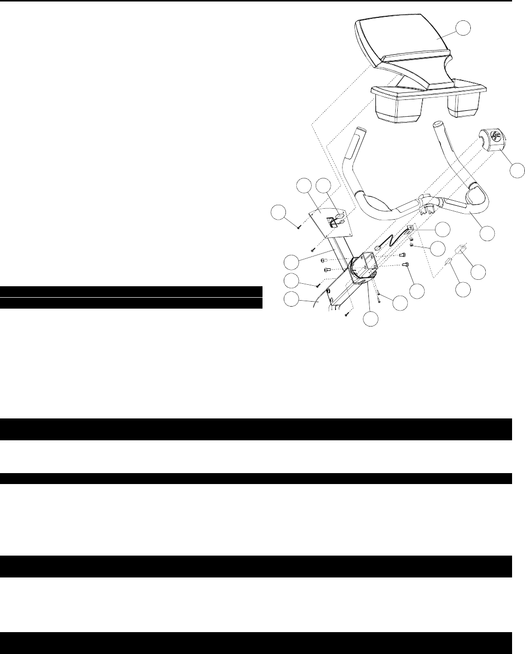
1. Remove the four MOUNTING SCREWS (A) securing the
DISPLAY CONSOLE (B) to the DISPLAY CONSOLE
MOUNTING BRACKET (C). Set the MOUNTING
SCREWS aside.
2. Carefully raise the DISPLAY CONSOLE (B) off of the
DISPLAY CONSOLE MOUNTING BRACKET (C).
Disconnect all CONNECTORS (D) from the back of the
DISPLAY CONSOLE. Set the DISPLAY CONSOLE
aside.
3. Remove the four MOUNTING SCREWS (E) securing the
FRONT POLAR CAP (F) to the REAR POLAR CAP (G).
Remove the FRONT POLAR CAP and set it and the four
MOUNTING SCREWS aside. Slide the REAR POLAR
CAP down the MONOCOLUMN (H) until it rests on the
CONSOLE EXTENSION TUBE (J).
4. Remove the four MOUNTING SCREWS (K) securing the
HANDLEBARS (L) to the MONOCOLUMN (H). Set the
MOUNTING SCREWS aside.
5. Carefully remove the HANDLEBARS (L) from the
MONOCOLUMN (H). Disconnect the HEART RATE
CABLE CONNECTOR if equipped. Set the
HANDLEBARS aside.
NOTE: BE CAREFUL NOT TO PULL ON THE
HEART RATE CABLE.
6. Locate the “L” BRACKET CABLE ASSEMBLY (M) and
the two WELLNUTS (N). Insert the two WELLNUTS into
the two open holes on the “L” BRACKET as shown.
7. Feed the “L” BRACKET CABLE ASSEMBLY (M), 3-PIN CONNECTOR end first, into the MONOCOLUMN (H) and up
through the CONSOLE EXTENSION TUBE (J) access hole.
8. Align the “L” BRACKET (M) with the mounting holes located on the bottom side of the MONOCOLUMN near the top
most end of the MONOCOLUMN (H). The POLAR RECEIVER JACK should face the inside of the MONOCOLUMN.
Secure the “L” BRACKET using the two supplied MOUNTING SCREWS (O).
NOTE: CAREFULLY GRIP THE WELLNUTS (N) INSIDE THE MONOCOLUMN (H) TO ENSURE THE WELLNUTS DO
NOT SPIN UPON TIGHTENING THE MOUNTING SCREWS (O).
9. Carefully replace the HANDLEBARS (L) in reverse order of removal. Re-connect the HEART RATE CABLE if
equipped. Tighten the four SCREWS (K) to 28-32 ft. lbs.
NOTE: BE CAREFUL NOT TO PINCH ANY WIRES WHEN INSTALLING THE HANDLEBARS (L).
10. Slide the foam POLAR RECEIVER COVER (P) over the POLAR RECEIVER (Q). Note the red dot on the POLAR
RECEIVER. Insert the POLAR RECEIVER PLUG into the POLAR RECEIVER JACK of the “L” BRACKET CABLE
ASSEMBLY (M). Position the POLAR RECEIVER with the red dot facing upward.
11. Slide the REAR POLAR COVER (G) up to meet the HANDLEBARS (L). Position the FRONT POLAR CAP (F) over
the REAR POLAR CAP and secure using the four previously removed SCREWS (E).
NOTE: THE LOGO ON THE FRONT POLAR COVER (F) MUST BE FACING UPWARD FOR CORRECT FRONT
POLAR CAP ORIENTATION.
12. Connect all CONNECTORS (D) leading from the CONSOLE EXTENSION TUBE (J) access hole to the back of the
DISPLAY CONSOLE (B). Carefully place the DISPLAY CONSOLE onto the DISPLAY CONSOLE MOUNTING
PLATE (C). Secure the DISPLAY CONSOLE to the DISPLAY CONSOLE MOUNTING PLATE using the four
previously removed MOUNTING SCREWS (A). Tighten the MOUNTING SCREWS securely.
NOTE: BE CAREFUL NOT TO PINCH ANY WIRES WHEN INSTALLING THE DISPLAY CONSOLE (B) TO THE
DISPLAY CONSOLE MOUNTING PLATE (C).
M051-00K63-A029
P
Q
L
F
B
A
DC
J
E
H
G
K
O
M
N


