


Using (2) #10 x 1/2" Phillips screws from
the top and (4) #6 x 3/8 Phillips screws
from the bottom, secure the bridge cover
to the bridge/console assembly. Be sure
to align the edges of the top and bottom
covers before tightening the screws.
Tighten the screws securely but do not
over tighten them.
AB
C
D
C
E
Actual Size
Actual Size
Actual Size
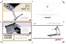
Level the treadmill using the leveling feet (A). Once the treadmill is level, lock the feet in place with the jam nuts.
If necessary, use the provided hex key wrench to center the striding belt. See
How to Center the Striding Belt
page in
the
How To
section of the user manual (B).
Feed one end of the console cable down through the center hole of the right upright (A) and then out the bottom
cable access hole as shown (B). Carefully pull approximately 18" of cable through the cable access hole and connect
the cable jack to the motor controller board as shown (B). Connect the remaining cable jack (near the bridge assembly)
to the console board located at the bottom of the display console (A). Route the console cable through the cable clips
as shown. Feed any excess cable into the center hole of the right upright.
5
A
6
4
7
8
9
A
Hardware Needed
Hardware Needed
Hardware Needed
Hardware Needed
B
B
Bolt the bridge/console assembly to the
uprights using (4) M10 x 25mm bolts and
(4) M10 internal tooth washers as shown.
Tighten the (4) bolts securely.
Now tighten the bottom (8) upright bolts
(from step 3) securely.
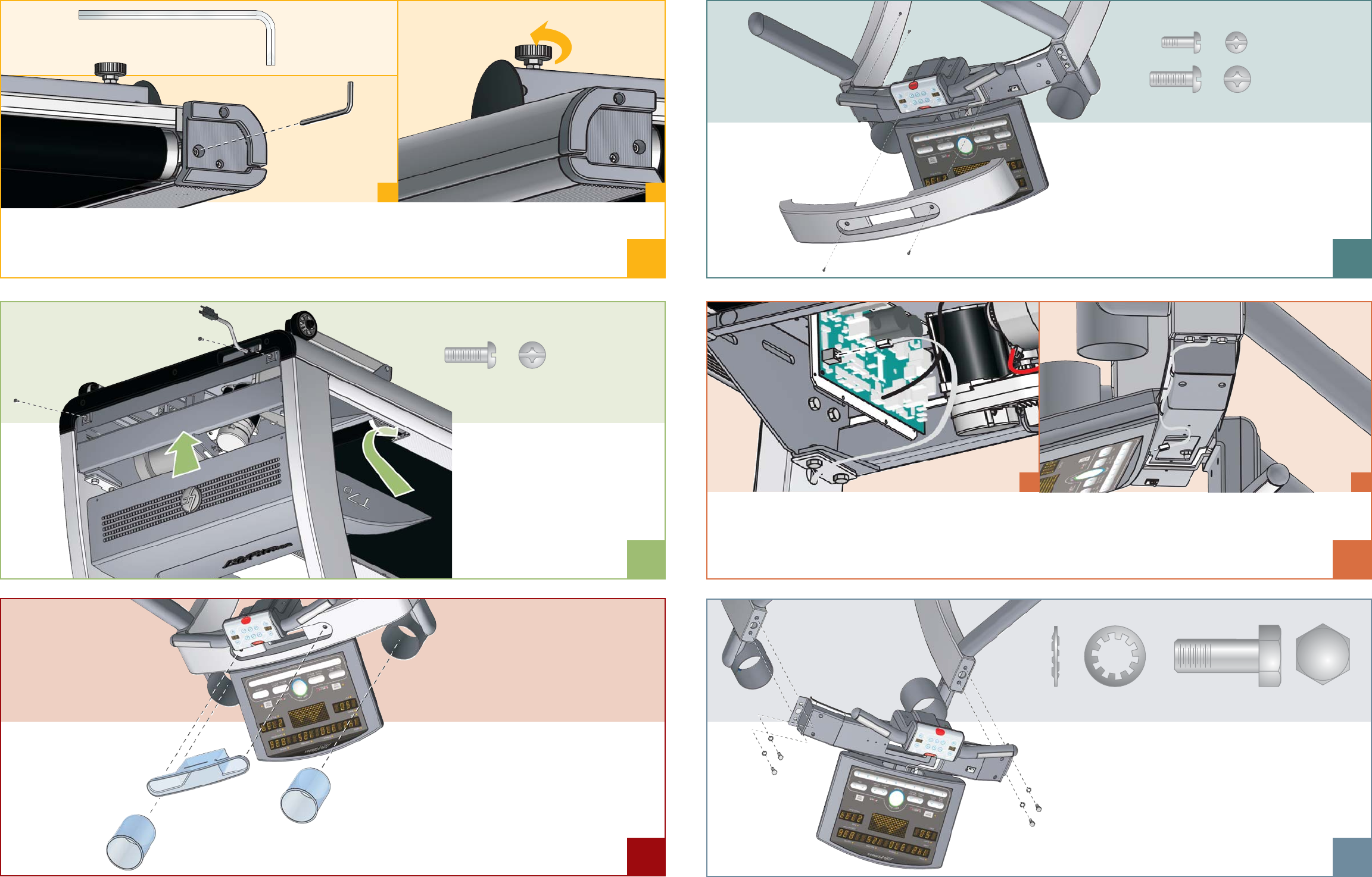
Insert the water bottle holders and CD tray
into their respective locations as shown.
Press firmly to ensure they are fully seated.
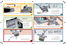
Re-install the motor cover.
With the front of the motor
cover tilted upward, slide the
motor cover into the clips and
lower the front down to the
frame. Secure the motor
cover using the (2) previously
removed screws. Tighten the
screws securely but do not
over tighten them.
PM-009-05 insturctions 9/27/05 9:19 AM Page 2