


5. Connect the CONNECTOR (J) leading from the HANDLE-
BAR ASSEMBLY (E) with the CONNECTOR (J) leading from
the SEAT ASSEMBLY (F). Be sure the connectors fully lock.
CAUTION: To ensure that your handsensor heart rate
works properly, secure the HEART RATE CABLE (K) into
the CABLE TIE CLIPS (G). Note the routing of the
HEART RATE CABLE so as to not pinch the HEART
RATE CABLE between the SEAT and the SEAT ASSEM-
BLY during assembly.
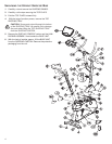
6. Locate the SEAT BOTTOM (L). Align the SEAT BOTTOM
mounting holes with those in the LOWER SEAT SUPPORT
TUBES (M). Secure the SEAT BOTTOM using four 2"
PHILLIPS SCREWS (6) and LOCK WASHERS (7). Tighten
the SCREWS securely.
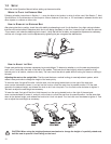
7. Align the guide rollers located on the underside of the SEAT
ASSEMBLY (F) with the SEAT EXTRUSION (N). Carefully
guide the SEAT ASSEMBLY onto the SEAT EXTRUSION.
Slide the SEAT ASSEMBLY fully forward. Connect the WIRE
(O) leading from the user left side of the SEAT ASSEMBLY
to the jack located at the left front of the SEAT EXTRUSION.
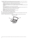
8.
In the hole located in the user right side of the SEAT EXTRU-
SION (J), behind SEAT ASSEMBLY (F), install one 1-3/8"
BUTTON HEAD SCREW with locktite (7), two 15/16" FLAT
WASHERS (8), one RUBBER BUMPER SLEEVE (9) and one
1" RUBBER BUMPER (10) as shown.
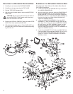
9. Mount the SEAT ADJUSTMENT LEVER (P) to the user right
side of the SEAT ASSEMBLY (F) using two 3/4" PHILLIPS
SCREWS (11). Tighten the SCREWS securely.
10. Secure the SEAT BACK (Q) to the UPPER SEAT SUPPORT
TUBES (R) using four 2" PHILLIPS SCREWS (6) and LOCK
WASHERS (7). Tighten the SCREWS securely.
11. Locate the SEAT EXTRUSION ENDCAP (S). Secure the
SEAT EXTRUSION ENDCAP to the SEAT EXTRUSION (N)
using two 1/2" PHILLIPS SCREWS (12).
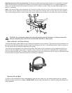
12. Locate the MONOCOLUMN (T). Cut the WIRE TIE securing
the WIRE (U) to the bottom of the MONOCOLUMN. Slide
the MONOCOLUMN COVER (V) onto the MONOCOLUMN
as shown. Slide the MONOCOLUMN COVER up to the
HANDLEBAR TUBE (W).
13. Locate and insert the GROMMET (X) into the SIDE ACCESS
HOLE (Y) of the MONOCOLUMN (T). Pull the WIRE (U) out
through the SIDE ACCESS HOLE.
14. With the HANDLEBAR TUBE (W) facing the rear of the unit
as shown, slide the MONOCOLUMN (T) into the MONO-
COLUMN BRACKET (Z) of the BASE UNIT (C). Slide the
MONOCOLUMN down until it is fully seated. Secure the
MONOCOLUMN to the MONOCOLUMN BRACKET using
two 3-15/16" HEX HEAD BOLTS (13) and three THICK FLAT
WASHERS (14) (as shown) from the front side of the
MONOCOLUMN and two 2-3/8" HEX HEAD BOLTS (15)
and THICK FLAT WASHERS (14) from the user left side of
the MONOCOLUMN BRACKET. Tighten the BOLTS secure-
ly.
CAUTION: Be careful not to pinch the WIRE(s) (AA)
leading from the MONOCOLUMN BRACKET (Z) when
inserting the MONOCOLUMN (T) into the MONOCOL-
UMN BRACKET.
15. Connect the WIRE(s) (AA) leading from the MONOCOLUMN
BRACKET (Z) to the corresponding WIRE (U) from the SIDE
ACCESS HOLE (Y) of the MONOCOLUMN. Slide the
MONOCOLUMN COVER (V) downward to the meet the
MAIN SHROUDS (BB). Secure the MONOCOLUMN COVER
to the MAIN SHROUDS using four 1/2" PHILLIPS SCREWS
(12) and matching FLAT WASHERS (16). Tighten the
SCREWS securely. Do not overtighten the SCREWS.
16. Locate the DISPLAY CONSOLE BRACKET (CC) and
ACCESSORY TRAY (DD). While holding the WIRE(s)/CON-
NECTOR (EE), cut the wire tie securing the CONNECTOR
to the MONOCOLUMN (T). Position the DISPLAY CON-
SOLE BRACKET and ACCESSORY TRAY near the top of
the MONOCOLUMN. Feed the WIRE(s)/CONNECTOR lead-
ing from the TOP ACCESS HOLE (FF) of the MONOCOL-
UMN through the center hole of the DISPLAY CONSOLE
BRACKET and the ACCESSORY TRAY. Secure the DIS-
PLAY CONSOLE BRACKET and the ACCESSORY TRAY to
the MONOCOLUMN using two 1" PHILLIPS SCREWS (17)
and matching FLAT WASHERS (18). Tighten the SCREWS
securely.
CAUTION: Be careful not the pinch the WIRE(s)/CON-
NECTOR (EE) leading from the MONOCOLUMN (T)
when securing the DISPLAY CONSOLE BRACKET (Z)
and ACCESSORY TRAY (DD) to the MONOCOLUMN.
NOTE: Be careful not to let the WIRE(s)/CONNECTOR (EE)
fall into the MONOCOLUMN (T).
17. Remove the DISPLAY CONSOLE (GG) from its shipping
carton. Position the above the ACCESSORY TRAY (DD).
Connect the WIRE(s)/CONNECTOR (EE) leading from the
DISPLAY CONSOLE BRACKET (Z) to the corresponding
JACK(s) located on the back of the DISPLAY CONSOLE.
Secure the DISPLAY CONSOLE to the DISPLAY CONSOLE
BRACKET using four 1/2" PHILLIPS SCREWS (12). Tighten
the SCREWS securely. Do not overtighten the SCREWS.
18. Locate the HANDLEBAR ASSEMBLY (HH). Position the
HANDLEBAR ASSEMBLY near the top of the HANDLEBAR
TUBE (W). Slide the HANDLEBAR ASSEMBLY fully into the
HANDLEBAR TUBE. Secure the HANDLEBAR ASSEMBLY
to the HANDLEBAR TUBE using four 5/8" BUTTON HEAD
SCREWS (3) and matching FLAT WASHERS (4). Tighten
the SCREWS securely.
19. Locate the RIGHT PEDAL (JJ) (marked with an "R") and
PEDAL STRAP (KK) (marked with an "R"). With the side of
the PEDAL STRAP marked with an R facing upward, slide
the slotted end of the PEDAL STRAP through the left slot in
the PEDAL. Fasten one of the slots onto the TAB located
under the left slot of the PEDAL. Bend the PEDAL STRAP
upward and slide the remaining end of the PEDAL STRAP
through the right slot in the PEDAL and into the STRAP
ADJUSTMENT CLIP. The PEDAL STRAP should securely
engage the STRAP ADJUSTMENT CLIP.
20. Install the RIGHT PEDAL (JJ) to the USER RIGHT CRANK
ARM (LL). Repeat for the LEFT PEDAL (MM) (marked with
an "L") and PEDAL STRAP (NN) (marked with an "L").
NOTE: The LEFT PEDAL (MM) has reverse threads.
21. Position the unit in the desired location for use. The unit can
be easily moved into place by lifting the rear of the unit and
rolling it on the front rollers. Level the unit before use. Refer
to the leveling instructions stated in the operations portion of
this manual.
7