


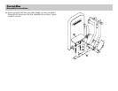


NOTE: Some components have been removed from the illustration for
clarity.
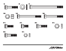
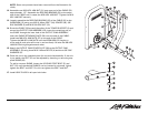
12. Assemble one M10 HEX JAM NUT (31) onto one end of the CABLE (32)
approximately 1/2”. Assemble the ROD END BEARING (33) to the same
end of the CABLE until it meets the M10 HEX JAM NUT. Tighten the M10
HEX JAM NUT securely.
13. Loosely assemble the ROD END BEARING (33) of the CABLE (32) to the
WORKARM (15) using one M10 X 40mm BOLT (34), SPACER (35), 3/8"
SAE WASHER (5) and M10 NYLOCK NUT (10).
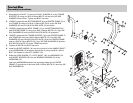
14. Route the CABLE (32) around the pulley of the TOWER SUPPORT (3) and
around the OUTPUT CAM ASSEMBLY (B). Insert the remaining end of
the CABLE through the inner hole of the OUTPUT CAM ASSEMBLY.
Insert the CABLE RETAINING PLATE (36) over the end of the CABLE.
Install two M8 HEX JAM NUTS (37) to the end of the CABLE.
Tighten the M8 HEX JAM NUTS until the WORKARM (15) begins to
move and all push pins still move in and out freely. Be sure the M8 HEX
JAM NUTS are tight against each other.
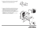
15. Attach the OUTPUT CAM COVER PLATE (38) to the OUTPUT CAM
ASSEMBLY (B) using three M10 X 45mm BOLTS (4) and three 3/8" SAE
WASHERS (5).
16. Place the unit in the intended place for use and check stability. If the unit
is not stable, the FEET (D) can be adjusted by inserting or removing sup-
plied SHIMS (39).
To add or remove SHIMS, loosen the LEVELING FOOT BOLT (E) and
NUT (10) until the desired SHIM(S) can be inserted or removed. Lightly
tighten the BOLT and NUT. Do not over-tighten the BOLT and NUT.
17. Install HOLE PLUGS in all open bolt holes.