


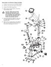

ASSEMBLING THE RECUMBENT
EXERCISE BIKE
Tools Required: Metric Wrench Set, Metric Allen Wrench
Set, Phillips Screwdriver
1. 1. Locate and install the two LEVELER FEET (A) to the
bottom of the REAR STABILIZER (B).
2. Attach the REAR STABILIZER (B) to the BASE UNIT
(C) using two 2-3/8" BUTTON HEAD SCREWS (1)
from the top of the REAR STABILIZER BRACKET (D)
and two 13/16" BUTTON HEAD SCREWS (2) from the
front side of the REAR STABILIZER BRACKET.
Tighten the SCREWS securely.
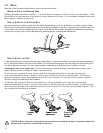
3. Locate the HANDLEBAR ASSEMBLY (E) and the
SEAT ASSEMBLY (F). With the handlebars facing
upward and forward, align the mounting holes of the
HANDLEBAR ASSEMBLY with those in the SEAT
ASSEMBLY. Secure the HANDLEBAR ASSEMBLY to
the SEAT ASSEMBLY using four 5/8" BUTTON HEAD
SCREWS (3) and FLAT WASHERS (4). Tighten the
SCREWS securely.
4. Locate the SEAT BOTTOM (G). Align the SEAT BOT-
TOM mounting holes with those in the LOWER SEAT
SUPPORT TUBES (H). Secure the SEAT BOTTOM
using four 2" PHILLIPS SCREWS (5) and LOCK
WASHERS (6). Tighten the SCREWS securely.
5. Align the guide rollers located on the underside of the
SEAT ASSEMBLY (F) with the SEAT EXTRUSION (J).
Carefully guide the SEAT ASSEMBLY onto the SEAT
EXTRUSION. Slide the SEAT ASSEMBLY fully for-
ward.
6. In the hole located in the user right side of the SEAT
EXTRUSION (J), behind SEAT ASSEMBLY (F), install
one 1-3/8" BUTTON HEAD SCREW with locktite (7),
one 15/16" FLAT WASHER (8), and one 1" RUBBER
BUMPER (9) as shown.
7. Mount the SEAT ADJUSTMENT LEVER (K) to the user
right side of the SEAT ASSEMBLY (F) using two 3/4"
PHILLIPS SCREWS (10) and LOCK WASHERS (11).
Tighten the SCREWS securely.
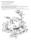
8. Secure the SEAT BACK (L) to the UPPER SEAT SUP-
PORT TUBES (M) using four 2" PHILLIPS SCREWS
(5) and LOCK WASHERS (6). Tighten the SCREWS
securely.
9. Locate the SEAT EXTRUSION ENDCAP (N). Secure
the SEAT EXTRUSION ENDCAP to the SEAT EXTRU-
SION (J) using two 1/2" PHILLIPS SCREWS (12).
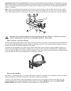
10. Locate the MONOCOLUMN (O). Insert the WIRE (P)
leading from the SIDE ACCESS HOLE (Q) of the
MONOCOLUMN fully into the MONOCOLUMN.
Remove the GROMMET (R) from the SIDE ACCESS
HOLE and set it aside.
11. Slide the MONOCOLUMN COVER (S) onto the
MONOCOLUMN (O) as shown. Slide the MONOCOL-
UMN COVER up to the HANDLEBAR TUBE (T).
12. Re-insert the GROMMET (R) into the SIDE ACCESS
HOLE (Q) of the MONOCOLUMN (O). Pull the WIRE
(P) back out through the SIDE ACCESS HOLE.
13. With the HANDLEBAR TUBE (T) facing the rear of the
unit as shown, slide the MONOCOLUMN (O) into the
MONOCOLUMN BRACKET (U) of the BASE UNIT (C).
Slide the MONOCOLUMN down until it is fully seated.
Secure the MONOCOLUMN to the MONOCOLUMN
BRACKET using two 3-15/16" HEX HEAD BOLTS (13)
and three LOCK WASHERS (14) (as shown) from the
front side of the MONOCOLUMN and two 2-3/8" HEX
HEAD BOLTS (15) and LOCK WASHERS (14) from
the user left side of the MONOCOLUMN BRACKET.
Tighten the BOLTS securely.
CAUTION: BE CAREFUL NOT TO PINCH THE
WIRE (V) LEADING FROM THE MONOCOLUMN
BRACKET (U) WHEN INSERTING THE MONO-
COLUMN (O) INTO THE MONOCOLUMN
BRACKET.
14. Connect the WIRE (V) leading from the MONOCOL-
UMN BRACKET (U) to the corresponding WIRE (P)
from the SIDE ACCESS HOLE (Q) of the MONOCOL-
UMN (O). Slide the MONOCOLUMN COVER (S)
downward to the meet the MAIN SHROUDS (W).
Secure the MONOCOLUMN COVER to the MAIN
SHROUDS using four 1/2" PHILLIPS SCREWS (12)
and matching FLAT WASHERS (6). Tighten the
SCREWS securely. Do not overtighten the SCREWS.
15. Remove the DISPLAY CONSOLE (X) from its shipping
carton. Position the above the DISPLAY CONSOLE
BRACKET (Y). Connect the WIRE (Z) leading from the
DISPLAY CONSOLE BRACKET to the corresponding
JACK(s) located on the back of the DISPLAY CON-
SOLE. Secure the DISPLAY CONSOLE to the DIS-
PLAY CONSOLE BRACKET using four 1/2" PHILLIPS
SCREWS (12). Tighten the SCREWS securely. Do not
overtighten the SCREWS.
16. Locate the PEDALS. Install the RIGHT PEDAL (AA)
(marked with an "R") to the USER RIGHT CRANK
ARM (BB). Repeat for the LEFT PEDAL (CC) (marked
with an "L").
NOTE: THE LEFT PEDAL (CC) HAS REVERSE
THREADS.
17. Locate the WATER BOTTLE BRACKET (DD). Secure
the WATER BOTTLE BRACKET to the underside of
the MONOCOLUMN (O) using two 3/8" PHILLIPS
SCREWS (16). Tighten the screws securely. Insert the
WATER BOTTLE (EE) into the WATER BOTTLE
BRACKET.
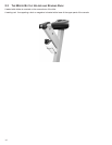
18. Position the unit in the desired location for use. The
unit can be easily moved into place by lifting the rear of
the unit and rolling it on the front rollers. Level the unit
before use. Refer to the leveling instructions stated in
the operations portion of this manual.
7