Kit No. GK62-00002-0071
Document No. M051-00K62-A208
2
22 Apr 2008
3. Place the crank extension at the twelve o’clock position.
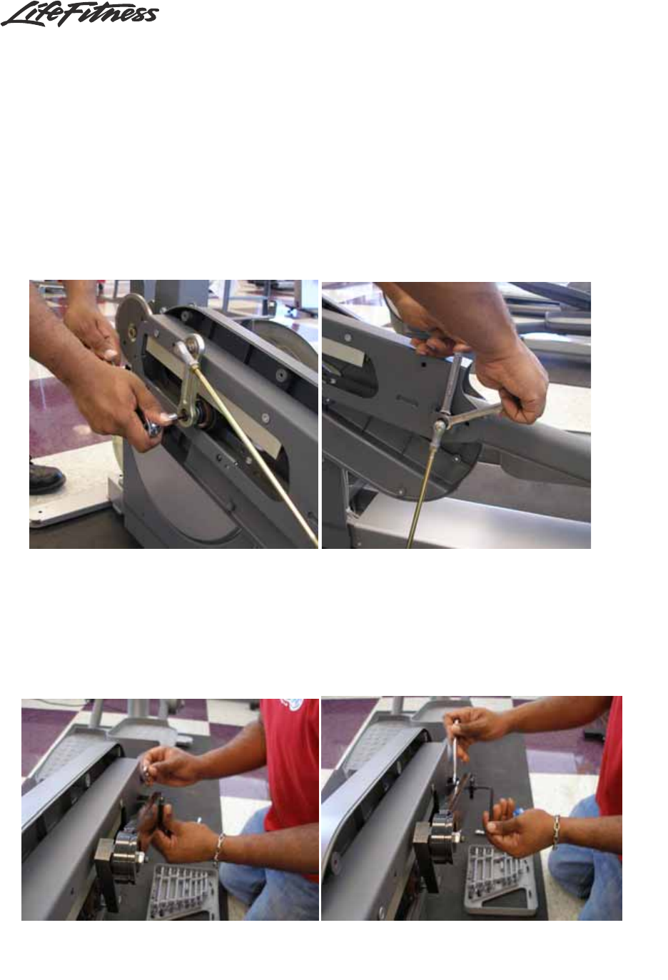
4. Remove the bolt that secures the crank extension to the crankshaft, as shown in
Figure 5.
5. Remove the hex nut, washer, bolt, and control link sleeve that secure the crank
extension to the control link assembly (see Figure 6). Discard everything except
the crank extension mounting bolt. Apply Loctite to the bolt.
5. Secure the new control link assembly in the twelve o’clock position with the
existing extension mounting bolt and the new hardware. Secure the crank extension
to the crankshaft using the existing extension mounting bolt, as shown in Figures 7,
8, and 9. Figure 10 shows the assembly installed. Torque the crank extension bolt to
50—55 ft-lbs (68—75 Nm).
Fig. 7: use the old crank extension mounting bolt Fig. 8: installing the new control link assembly
Fig. 5: removing the crank extension bolt Fig. 6: removing the control link assembly


