


1
How To...REMOVE AND REPLACE THE LIFEPULSE
DIGITAL HEART RATE SENSORS
Tools Required: Phillips screwdriver, standard screwdriver, 5/64” hex key wrench
WARNING: Turn the power off at the ON/OFF switch and disconnect the plug from the electrical
outlet prior to servicing any machine operating on AC current. Also be aware that there are two
sizes of sensor kits available. Refer to the chart shown in these instructions to ensure you have
the right kit for the product on which the sensors will be replaced.
NOTE: The kit you have received will come equipped with either 5/64” hex key button head screws or
Phillips head pan screws. Either can be used for sensor replacement procedures on all models of Life
Fitness exercise equipment equipped with Lifepulse
digital heart rate sensors. The treadmill handlebar
shown in the photographs are for demonstration purposes only. Replacement procedures as listed will
remain the same for all applications. ALWAYS REPLACE BOTH SETS OF SENSORS PROVIDED IN THE KIT.
Removing the existing Lifepulse digital heart rate sensors:
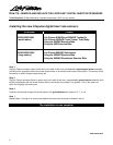
Step 1
Using a standard flat screwdriver, pry off the stainless steel sensor furthest
away from you as if you were the user gripping the Lifepulse heart rate
monitoring sensors (if screw access holes are already provided in the sensor
you wish to replace, simply remove the two screws and continue to Step 2).
This will be the sensor on which your fingertips rest during use. This sensor will
be referred to as the “ground sensor” (black or green wire) hereafter in these
instructions. The sensor closest to the user, on which the palm rests, will be
referred to as the “signal output sensor” (red or white wire).
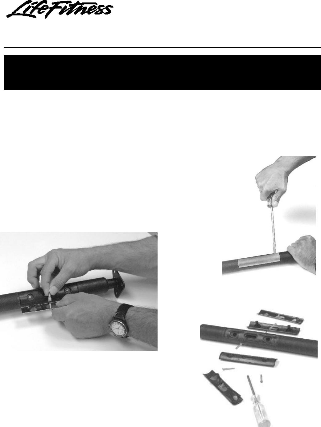
Step 2
Pull the ground sensor gently away from the molded plastic housing,
to which it was attached, to reveal a wire harness (black or green wire)
with a Faston connector attached to the back of the sensor. Unplug the
Faston connector from the ground sensor.
Step 3
Loosen and remove the two screws securing the two sensor molded
plastic housings to each other on the assembly. Lift the molded plastic
housings away from each other and unplug the Faston connector
attached to the back of the signal output sensor (red or white wire).