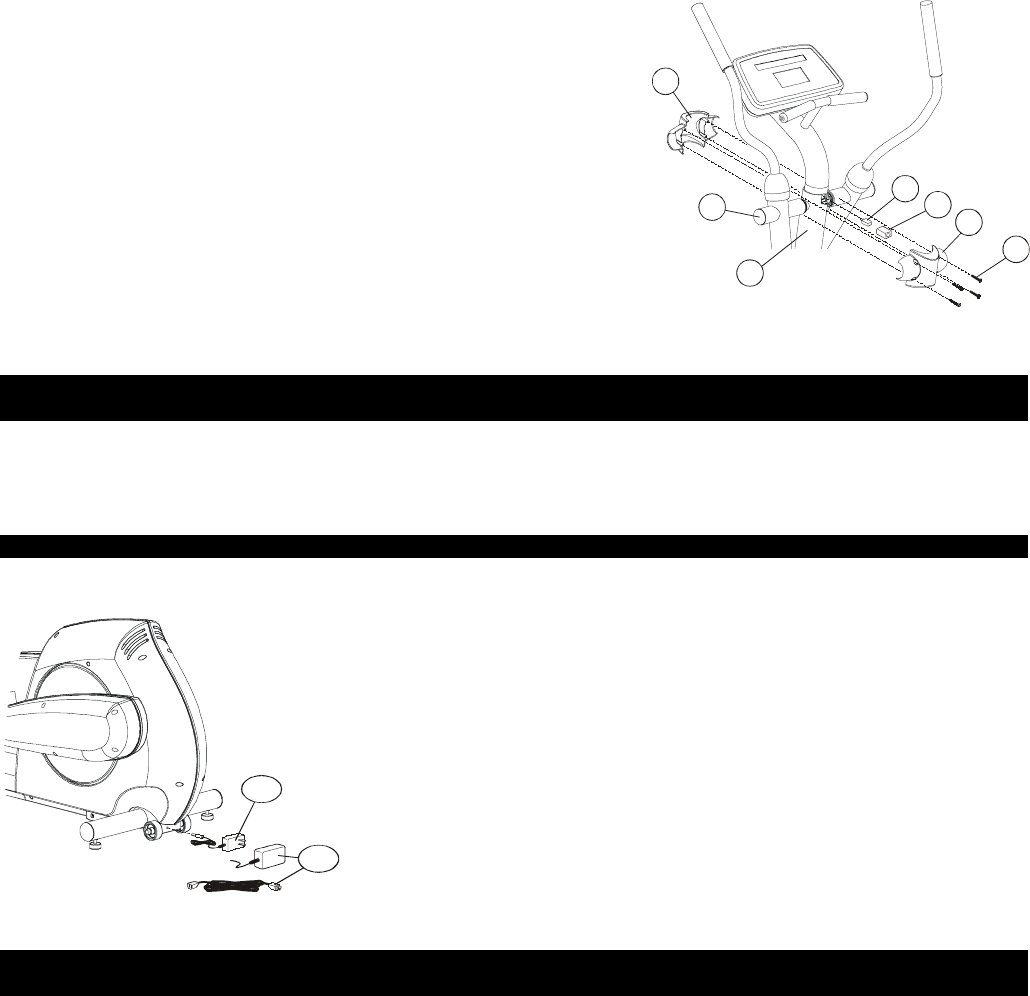
Step 9 (Model 5500HR Only)
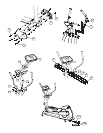
Locate the POLAR
®
RECEIVER (#14). Plug the POLAR RECEIVER
into the jack located at the front of the MONOCOLUMN (E) near the
DEAD SHAFT (F). Slide the FOAM ISOLATOR (#15) over the POLAR
RECEIVER.
Step 10
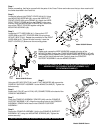
Locate the front and back MONOCOLUMN COVERS (#5, #6). Place
the FRONT MONOCOLUMN COVER (#5) over the PIVOT SHAFT (F)
at the top of the MONOCOLUMN (E).
(Model 5500HR Only)
With the wire positioned on top, carefully insert the POLAR RECEIVER
between the vertical ribs located inside the REAR MONOCOLUMN
COVER.
NOTE: THE POLAR RECEIVER WIRE MUST BE BE POSITIONED ON TOP WHEN INSERTED INTO
THE REAR MONOCOLUMN COVER.
Place the REAR MONOCOLUMN COVER (#6) on the opposite side of the FRONT MONOCOLUMN COVER to
cover the PIVOT SHAFT and CONSOLE SUPPORT ASSEMBLY MOUNTING BOLTS. Use four MOUNTING
SCREWS (#3) to secure the MONOCOLUMN COVERS together. Tighten the screws securely.
CAUTION: DO NOT OVER-TIGHTEN THE MOUNTING SCREWS (#3).
Step 11 (Model 5500HR Only)
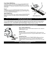
Position the Cross-Trainer into the desired location for use. Locate the
POWER SUPPLY (#13).
(Domestic Only)
Plug the connector end of the POWER SUPPLY (13A) into the Cross-
Trainer at the lower rear of the unit. Plug the POWER SUPPLY into a wall
outlet.
(International Only)
Plug the connector end of the TRANSFORMER (13B) into the Cross-
Trainer at the lower rear of the unit. Plug the LINE CORD into the
TRANSFORMER. Plug the pronged end of the LINE CORD into a wall
outlet.
CAUTION: REFER TO THE OPERATION MANUAL FOR
PROPER LINE CORD USEAGE.
Plane36
13A
13B
3
6
5
14
15
E
F
Model 5500HR Shown


