


5
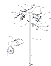
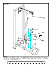
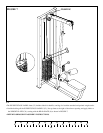
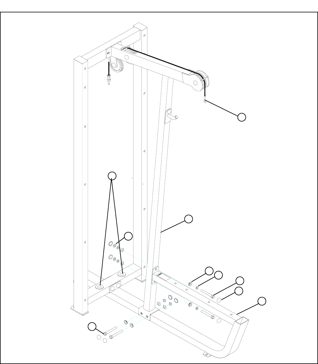
FIGURE 2
STEP 2:
• LOOSELY assemble the MAIN UPRIGHT (2) to the base of the BENCH FRAME (3) using four RH CAPS (27), two 3/8 X 3-3/
4” BOLTS (10), four 3/8” RH WASHERS (14) and two 3/8” LOW HEIGHT LOCK NUTS (11) as shown in FIGURE 2.
3/8 X 3-3/4” 10
9 3/8 X 2-3/4
27
14
13
2
11
3
• LOOSELY assemble the MAIN UPRIGHT (2) to the top tube of the BENCH FRAME (3) using four RH CAPS (27), two 3/8 X
2-3/4” BOLTS (9), four 3/8” SAE WASHERS (13), four 3/8” RH WASHERS (14) and two 3/8” LOW HEIGHT LOCK NUTS
(11) as shown in FIGURE 2.
• Securely tighten all loose frame connections made to this point, then proceed to snap RH CAPS
(27) over the RH WASHERS (14) on all tightened connections.
1A
1B