


IMPORTANT!
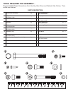
DO NOT DISCARD THE SHIP KIT. ALL NECESSARY COMPONENTS NEEDED TO COMPLETE
THE INSTALLATION ARE LOCATED IN THE SHIP KIT.
IMPORTANT!
NE JETEZ PAS LE KIT. IL CONTIENT TOUS LES ÉLÉMENTS NÉCESSAIRES POUR
L'INSTALLATION.
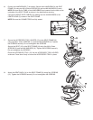
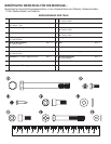
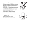
1. Position the unit base near its location for use.
2. Remove the USER LEFT CRANK ARM HOLE PLUG (A) and set it aside. Remove the
USER LEFT CRANK ARM SCREW (B) and slide the CRANK ARM (C) off the unit. Set
them both aside.
3. Remove the seven SCREWS (D) securing the USER LEFT FRONT SHROUD (E).
Remove the FRONT SHROUD and set it aside.
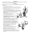
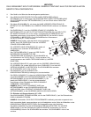
4. Slide the MONOCOLUMN ASSEMBLY (1) over the FRONT TUBE (F). Position and
align the NUT PLATE (19), TWO-HOLE PLATE (20) and ONE-HOLE PLATE (21) at the
front and back of the MONOCOLUMN ASSEMBLY as shown. Secure the MONOCOL-
UMN ASSEMBLY using three M10 x 90mm SCREWS (2). Tighten the
SCREWS to 50-55 ft lbs.
NOTE: Be careful not to pinch wires when sliding the MONO-
COLUMN ASSEMBLY over the FRONT TUBE.
Re-install the USER LEFT FRONT SHROUD (E) using the
seven previously removed SCREWS (D).
Re-install the CRANK ARM (C) using the USER LEFT
CRANK ARM SCREW (B) previously removed. Tighten
the SCREWS to 30-33 ft lbs. Replace the USER LEFT
CRANK ARM HOLE PLUG (A).
Slide the FRONT ACCESSORY TRAY (G) downward to
meet the FRONT SHROUDS (E). Secure the FRONT ACCESSORY
TRAY using one PHILLIPS SCREW (3) and M5 WASHER (18). Tighten the
SCREWS securely. Do not overtighten the SCREWS.
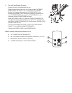
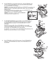
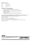
5. Cut the wire tie holding the cables to the CONSOLE BRACKET (H).
Position the DISPLAY CONSOLE (4) near the CONSOLE BRACKET (H).
Connect the MAIN CONSOLE CABLE (J), NETWORK CABLE (K) and
GROUND WIRE (L) leading from the MONOCOLUMN ASSEMBLY (1) to
their respective locations in the back of the DISPLAY CONSOLE.
NOTE: If using C-SAFE, connect the NETWORK CABLE to the
BLACK JACK. If using ETHERNET, connect the NETWORK
CABLE to the SILVER JACK.
For units with Engage Consoles (15” LCD)
Connect the COAXIAL CABLE (M) leading from the MONOCOL-
UMN ASSEMBLY (1) to the back of the DISPLAY CONSOLE.
NOTE: Be sure all CONNECTORS are fully seated.
Bundle and wire-tie unused cables to the side of the CONSOLE
BRACKET center post. Do not block any mounting holes.
Rest the DISPLAY CONSOLE on the CONSOLE BRACKET. Position the
REAR COVER (5) at the back of the DISPLAY CONSOLE and secure together
using four SCREWS (6). Tighten the SCREWS securely. Do not overtighten
the SCREWS.