


#$ % "$# "#
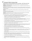
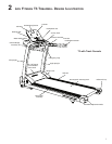
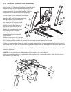
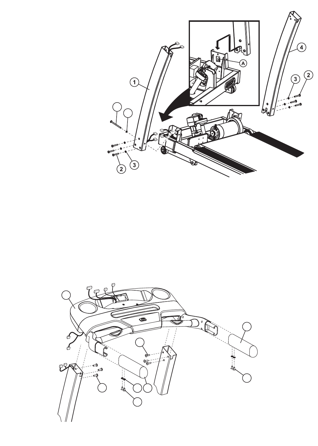
Remove the motor cover by removing four Phillips screws. Locate
the left upright (1). Position the left upright near the left upright
bracket and attach the wire connectors that lead from the
bottom of the left upright and the left upright bracket. Be
sure the connectors are fully seated together. Feed any
excess wire into the hollow inside of the left upright.
Put the uprights in their brackets by first inserting
them at an angle tilting away from the treadmill,
then fitting their upper rectangular slots over
the bracket’s tabs (A) and straightening
them, then lowering them fully into posi-
tion. Secure the left upright to the left
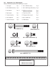
upright bracket using three M8 x 60mm
Bolts (2) and three Star Washers (3)
through the bottom and one M8 X
120mm Bolt (13) and one 25mm
Washer (14) through the side. Leave
the bolts finger-tight at this time.
%$ Do not pinch the wire when
attaching the left upright to the left
upright bracket.
Secure the right upright (4) to the right
upright bracket using three M8 x 60mm Bolts (2) and three Star Washers (3) through the bottom and one M8 X 120mm
Bolt (13) and one 25mm Washer (14) through the side. Leave the bolts finger-tight at this time.
Position the console bridge (5) near the top of the uprights. Attach the wire connectors leading from the left upright and
the console bridge. Be sure the connectors are fully seated together. Feed any excess wire into the hollow inside the left
upright.
Attach the console bridge to the uprights using six M8 x 15mm Tapered Bolts (9), three for each upright. Leave the bolts
finger-tight at this time.
%$Do not pinch the wire when attaching the left upright to the console bridge.
Attach one handlebar extension (7) on each side of the console bridge, using two black M8 x 15mm (8) Bolts and two
Star Washers (3) on each side.
13
14
3
9
9
7
8
8
7
5
10