8
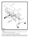
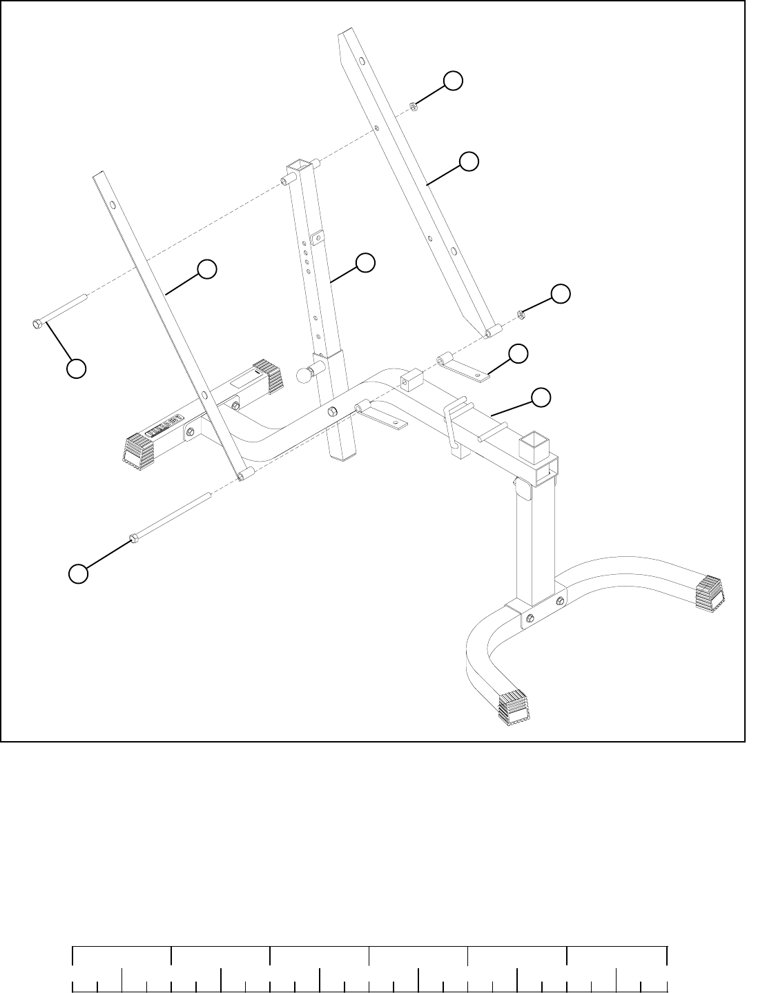
STEP 4:
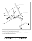
FIGURE 4
0
1
2
345
6
1/2 1/2 1/2 1/2 1/2 1/2
• Assemble the LEFT and RIGHT BACK PAD ANGLE (4 & 5) and two HINGE TABS (10) to the BENCH FRAME (1) using one 1/2 X 8”
BOLT (23) and one 1/2” LOW HEIGHT LOCK NUT (24) as shown in FIGURE 4.
10
1
2
5
4
1/2 X 8” 23
24 1/2” LOW HEIGHT
24 1/2” LOW HEIGHT
22 1/2 X 5-1/2”
• Assemble the LEFT and RIGHT BACK PAD ANGLE (4 & 5) to the ADJUSTABLE SLIDE (2) using one 1/2 X 5-1/2” BOLT (22) and
one 1/2” LOW HEIGHT LOCK NUT (24) as shown in FIGURE 4.


