


650883-X
PUMP
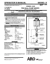
OPTION DESCRIPTION CHART
650883ā–āX
PACKINGMATERIAL
PLUNGERTYPE
SPRINGARRANGEMENT
(PACKINGS AREUPPER ANDLOWERUNLESS NOTED)
PACKING MATERIAL
P STAG'D (UPPER)
UHMW-PE(LOWER)
R
SPRING ARRANGEMENT
4 MULTIPLE WAVE SPRING
PLUNGER TYPE
7 HD SS W/HDCHROME PLATING
C HD SS W/CERAMIC COATING
4
X
3 GLASS FILLED
C UHMW-PE
G UHMW-PE/LEATHER STAG'D
GENERAL
DESCRIPTION
WARNING HAZARDOUS PRESSURE. Do not exceed maxiĆ
mum operating pressure of 4800 psi (331 bar) at 120 psi (8.3
bar) inlet air pressure.
PUMP RATIO X
INLETPRESSURETO PUMPMOTOR
=
MAXIMUMPUMP
FLUIDPRESSURE
Pumpratio isan expression oftherelationship betweenthe pumpmotor areaandthe
lowerpumpendarea.EXAMPLE:When120p.s.i.(8.3bar)inletpressureissuppliedto
the motorof a40:1 ratio pumpit willdevelop amaximum of 4800p.s.i. (331bar) fluid
pressure (atno flow)- asthe fluidcontrol isopened, theflow ratewill increaseas the
motor cycle rate increases to keep upwith the demand.
WARNING Refer to general information sheet for additional
safety precautions and important information.
• TheTwo-Ball pumpsare primarilydesigned forthepumping ofmeĆ
dium viscosity fluids, Stainless Steel construction offers compatiĆ
bility with a wide range of fluids. The two-ball design provides
better priming of the lower foot valve. The double acting feature is
standard in all ARO industrial pumps, material is delivered to the
pump discharge outlet on both the up and down stroke.
• The motoris connected tothe lowerpump end byaspacer section.
This allows for lubrication of the upper packing gland andprevents
motor contamination because of normal wear and eventual leakĆ
age through the material packing gland. Be sure the solvent cup is
adequately filled with lubricant to protect the upper packings and
insure longest service life.
TROUBLE SHOOTING
Pump problems can occur in either the Air Motor Section or the Lower
Pump EndSection, usethese basic guidelinesto helpdetermine which
section is affected.
If the pump will not cycle.
• Be certain to first check for non-pump problems including kinked,
restrictive or plugged inlet/outlet hose or dispensing device. DeĆ
pressurize the pump system and clean out any obstructions in the
inlet/outlet material lines.
• Refer to the motormanual fortrouble shootingif thepump doesnot
cycle and/or air leaks from the air motor.
If the pump cycles but does not deliver material.
• Refer to the lower pump end manual for further trouble shooting.
PUMP
CONNECTION – UPPER / LOWER
NOTE: All threads are right hand.
1. Lay the pump assembly on a workbench.
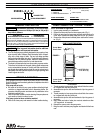
2. Remove the three nuts from the three spacer rods. (Fig. 1)
3. Pull the air motor from the lower pump enduntil motor piston rod is
in the ``down" position and lower pump end rod is in ``up" position.
4. Remove the cotter pins and unthread piston rodsfrom the connecĆ
tor. (Fig. 2)
Lower Pump
Piston Rod
Pump Motor
Piston Rod
CONNECTOR
92226
COTTER PIN
Y15–46–C (2)
PUMP CONNECTOR DETAIL
FIGURE 2
REASSEMBLY
1. Thread connector to pump motor piston rod until hole thru connecĆ
tor is aligned with hole thru piston rod.
2. Assemble cotter pin thru hole and bend ends of pin into groove of
connector.
3. Thread connector to lower pump piston rod until hole thru connecĆ
tor is aligned with hole thru piston rod.
4. Assemble cotter pin thru hole and bend ends of pin into groove of
connector.
5. Note: Heads and ends of cotter pins must not extend more than
.125" beyond o.d. of connector.
6. Reinstall the spacer rods to the pump motor.
7. Bring the motor and lower pump together and retain with the three
nuts.
PN 97999-658
15'&6).81&45"(h%611&3
15'&-08&3
6).81&15'&
15'&