


ASSEMBLY INSTRUCTION
Tools Required to Assemble the Machine: Two Adjustable Wrenches and Allen Wrenches.
NOTE: It is strongly recommended this machine to be assembled by two or more people to
avoid possible injury.
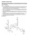
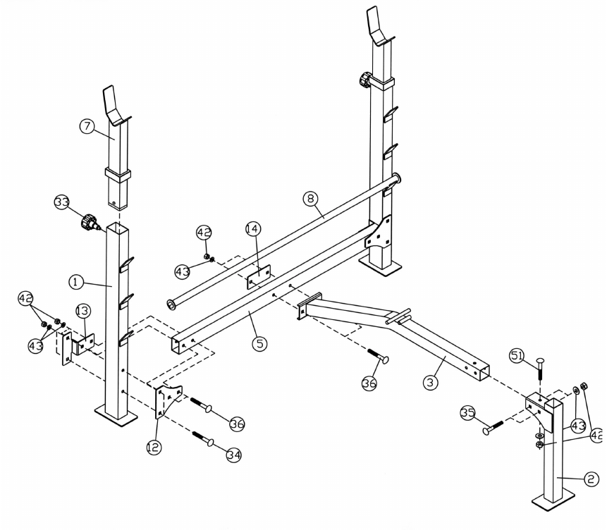
STEP 1 (See Diagram 1)
A.) Connect the Rear Upright Beams (#1) by a Cross Brace (#5) in the mid-span. Align the holes
and secure them with one Triangle Bracket (#12), one Bent Bracket (#13), two M10 x 3 ½”
Carriage Bolts (#34), two M10 x 2 3/8” Carriage Bolts (#36), four ∅ ¾” Washers (#43), and
four M10 Aircraft Nuts (#42) on each end of the Cross Brace.
B.) Attach the Front Stabilizer (#2) to the front of the Main Seat Support (#3). Secure it with one
M10 x 2 ½” Carriage Bolt (#51), two M10 x 2 ¾” Carriage Bolts (#35), ∅ ¾” Washers (#43),
and M10 Aircraft Nuts (#42).
C.) Attach the back of the Main Seat Support (#3) to the Cross Brace (#5). Secure it with one
Bracket (#14), two M10 x 2 3/8” Carriage Bolts (#36), ∅ ¾” Washers (#43), and M10 Aircraft
Nuts (#42).
D.) Insert two Crutches (#7) into the top openings on the Upright Beams. Secure them with two
Lock Knobs (#33) through selected holes to obtain desired height of the Supports.
E.) Place Backrest Adjustment Bar (#8) between the two Upright Beams on the selected bar
holder to obtain desired incline of Backrest.
DIAGRAM 1
4