


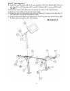
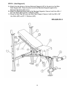
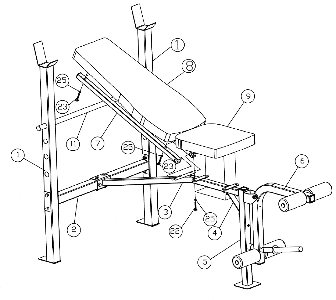
STEP 4 (See Diagram 4)
A.) Attach the side-holes on the two Backrest Supports (#7) to the pivot on the Main
Seat Support (#3). Place the other end of the Backrest Supports against the
Backrest Adjustment Bar (#11).
B.) Attach the Backrest Board (#8) to the Backrest Supports. Secure it with four M6 x 1
5/8” Hex Bolts (#23) and Ø ½” Washers (#25).
C.) Place the Seat Pad (#9) onto the Main Seat Support. Secure it with four M6 x 5/8”
Hex Bolts (#22) and Ø ½” Washers (#25).
DIAGRAM 4
8