


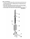
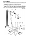
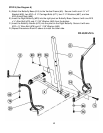
STEP 3 (See Diagram 3)
A.) Attach the Upper Frame (#4) onto the two Guide Rods (#18). Secure each Guide Rod
to the Upper Frame with on M10 x 1” Allen Bolt (#75) and ∅ ¾” Washer (#87). DO NOT
tighten the Nuts and Bolts yet.
B.) Place the Upper Frame (#4) onto the top of the Vertical Frame (#5). Secure it with one
5 ½” x 2” Bracket (#27), two M10 x 2 ¾” Carriage Bolts (#72), two ∅ ¾” Washers (#87),
and two M10 Aircraft Nuts (#89).
C.) Securely tighten all Nuts and Bolts previously installed.
D.) Attach the Backrest Board (#22) to the Backrest Support Frame (#12). Secure it with
two M8 x 1 5/8” Allen Bolts (#82) and ∅5/8” Washers (#86).
E.) Attach the Backrest Support Frame (#12) to the Vertical Frame (#5). Secure it with one
M10 x 3 ½” Allen Bolt (#73), two ∅¾” Washers (#87), and one M10 Aircraft Nut (#89).
F.) Thread the Long T-shape Lock Pin (#43) into the hole on the Vertical Frame. Insert the
Pin into selected hole on the Backrest Support Frame to obtain the desired Backrest
position.
G.) Attach the Seat Support Frame (#6) to the Vertical Frame (#5). Secure it with one M10
x 2 ¾” Carriage Bolt (#72), ∅¾” Washer (#87), and M10 Aircraft Nut (#89).
8