


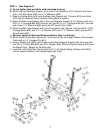
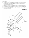


STEP 2 (See Diagram 2)
A.) Do not tighten Nuts and Bolts until instructed to do so.
B.) Attach the Leg Developer Support (#13) to the Front Stabilizer (#14). Secure it with three
M10 x 5/8” Allen Bolts (#63) and ¾” Washers (#66).
C.) Slide the Sliding Block (#15) onto the Main Seat Support (#4). Thread a M18 Lock Knob
(#42) into the selected hole to hold the Sliding Block in position.
D.) Attach the Main Seat Support (#4) to the Leg Developer Support (#13). Secure it with one
M10 x 2 ½” Carriage Bolt (#58) from the top, two M10 x 2 ¾” Carriage Bolts (#57) from the
side, three ¾” Washers (#66) and three M10 Aircraft Nuts (#68).
E.) Attach the Main Seat Support (#4) to the Cross Brace (#5). Secure it with two M10 x 2 3/8”
Carriage Bolts (#59), one 4 ¾” x 2” Bracket (#23), two ¾” Washers (#66), and two M10
Aircraft Nuts (#68).
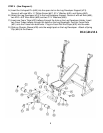
F.) Securely tighten all Nuts and Bolts installed in Step-1 and Step-2.
G.) Attach the two Squat Bar Catches (#7) to the back of the two Upright Beams. Secure each
Catch with a 4 ½” L-shaped Pin (#51).
H.) Insert a Weight Post (#24) into the hole on the Rear Diagonal Support (#8). Secure it with
one M10 x ¾” Allen Bolt (#62) and Ø ¾” Washer (#66). Slide an Olympic Sleeve (#30) onto
the Weight Post. Repeat for the other side.
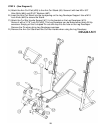
I.) Insert the Left & Right Bar Catches (#16 ), Left & Right Safety Catches (#18 )
into the selected holes on the Upright Beams (#1 & #2).
7