


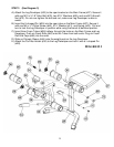
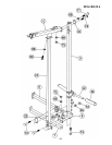
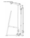
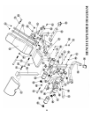

STEP 7 (See Diagram 7 & Cable Loop Diagram)
A.) Attach the 113 7/8” Upper Cable (#24) to the front opening on the Upper Frame (#11). Make
sure the ball stopper of the Cable is underneath the Frame.
B.) Attach a Pulley (#45) to the opening. Secure it with one M10 x 2 ½” Allen Bolt (#77), two 5/8”
Pulley Bushings (#65), and one M10 Aircraft Nut (#72).
C.) Draw the Cable along the Upper Frame towards the back of the machine to the open bracket
on the Upper Frame. Install a Pulley to the bracket with one M10 x 1 ¾” Allen Bolt (#80), two Ø
¾” Washers (#69), and one M10 Aircraft Nut (#72).
D.) Draw the Cable around the Pulley and downward. Install a Pulley to the Floating Pulley
Bracket (#23). Let the Bracket hanging for now. Pull the Cable around the Pulley and up to
the opening on the top of the Rear Vertical Frame (#9). Attach a Pulley to the opening and
secure it with one M10 x 2 3/8” Allen Bolt (#78), two ½” Pulley Bushings (#66), and one M10
Aircraft Nut (#72).
E.) Draw the Cable down to the Sliding Weight Post (#12) and secure it with one M10 x ¾” Allen
Bolt (#81), two ∅ ¾” Washers (#69) and one M10 Aircraft Nut (#72). Connect the Lat Bar
(#19) to the Cable with two Hooks (#46) and one Long Chain (#47).
15