


ASSEMBLY INSTRUCTION
Tools Required Assembling the Machine: Two Adjustable Wrenches and Allen
Wrenches
NOTE: It is strongly recommended two or more people assembling this machine to
avoid possible injury.
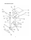
STEP 1 (See Exploded Diagram)
A.) Insert the Rear Base Frame (#2) into the rear of Main Base Frame (#1). Attach the Rear
Post (#3) to the Main Base Frame. Align the holes then secure them together with five
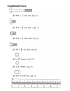
M10 x 5/8” Hex Bolts (#11) and Ø ¾” Washers (#22).
B.) Attach the Seat Post (#4) to the Main Base Frame (#1). Secure it with two M10 x 3” Hex
Bolts (#12), four Ø ¾” Washers (#22), and two M10 Aircraft Nuts (#15) from the side.
Secure it with two M10 x 5/8” Hex Bolts (#11), and Ø ¾” Washers (#22) from the top.
C.) Attach the Seat Pad (#10) to the Seat Bracket (#6). Secure it with four M8 x ¾” Hex Bolts
(#13) and Ø 5/8” Washers (#14).
D.) Attach the Seat Bracket (#6) to the Seat Post (#4). Then attached the Left and Right
Handlebars (#7) & (#8) to the Seat Post. Secure them with four M10 x 5/8” Allen Bolts
(#16) and Ø ¾” Washers (#22).
E.) Slide the Leg Support Frame (#5) onto the Rear Post. Use the Lock Knob (#9) to lock it at
desired height.
F.) Push two Foam Rolls (#17) onto the tube on the Leg Support Frame from both ends. Plug
a Foam Roll End Cap (#18) to each Foam Roll.
4