


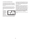
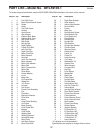

PART LIST—Model No. IMTL59105.1 R0406A
Key No. Qty. Description Key No. Qty. Description
1 2 Foot Rail Cover
2
2 Rear Roller Bracket Screw
3 30 Screw
4 1 Catch
5 10 Foot Rail Screw
6 2 Isolator
7 5 Hood Screw
8 8 Star Washer
9 2 Platform Bolt, Back
10 2 Platform Bolt, Front
11 4 Belt Guide Screw
12 2 Belt Guide
13 1 Left Upright
14 1 Right Upright
15 2 Frame Pivot Bolt
16 1 Left Foot Rail
17 1 Right Foot Rail
18 1 Motor Pivot Bolt
19 1 Motor Bracket
20 1 Handrail
21 1 Latch Pin Assembly
22 2 Motor Washer
23 1 Motor Star Washer
24 2 Motor Bolt
25 4 Motor Tension Bolt
26 1 Motor Belt
27 1 Drive Motor
28 2 Frame Washer
29 4 U-nut
30 2 Motor Nut
31 2
Lift Frame Bolt
32 7 Wheel Nut
33
16 1/2” Screw
34 1 Console
35 2 Fan Screw
36 1
Power Cord Assembly
37
1 Fan
38
1 Controller
39 1 Electronic Bracket
40 1 Filter Wire
41 1 Hood
42 1 Front Roller Bushing
43 1 Lift Frame
44 2 Base Endcap
45 1 Front Roller Bolt
46 1 Magnet
47 1
Front Roller
48 1 Walking Belt
49 1 Walking Platform
50 2
Handrail Endcap
51 1
Rear Roller
52 1
Left Rear Endcap
53 2 Rear Roller Bolt
54 1 Right Rear Endcap
5
5 1 Allen Wrench
56 1 Incline Stop Bracket
57 1 Ground Wire
58 1 Frame
59 1 Belly Pan
60 1 Reed Switch Screw
61 1 Reed Switch Clip
62 1 Front Roller Nut
63 1 Reed Switch
64 4 Handrail Bolt
65 4 Upright Bolt
66 5 Star Washer
67 4 Upright Star Washer
68 2 Caution Decal
69 1 Warning Decal
70 2 Platform Nut
71 1 Cable Tie
72 3 Cotter Pin
73 1 Latch Housing
74 3 Tie Clamp
75 3 Releasable Tie
76 1 Access Door
77 1 Wire Harness
78 1 Console Wire
79 1 Key/Clip
80 2 Front Wheel
81 2 Wheel Bolt
82 6 Base Pad
83 1 Static Decal
84 1
Upright Base
85 1 Console Base
86
1 Incline Motor Bolt
87 4 Hair Pin Cotter Pin
88 1 Incline Motor
89 4
Handrail Star Washer
90
2 Rear Roller Bracket
91
1 Chest Pulse Sensor
92 1 Pulse Receiver
93 2 Pulse Receive Screw
94 1 Silver Ground Screw
95 1 Book Holder
96 1 Chest Pulse Strap
97 4 Wheel Spacer
98 4 Isolator Washer
# 1 6” Blue Wire, 2F
#
1
6” Red Wire, M/F
# 1 4” Black Wire, M/F
# 1 4” Blue Wire, M/F
#
1
4” Blue Wire, 2F
#
1
User’s Manual
“#” indicates a non-illustrated part.
Specifications are subject to change without notice.
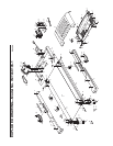
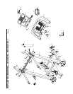
To locate the parts listed below, see the EXPLODED DRAWING attached in the center of this manual.
27