


6
5
4
84
84
57
Metal
Bracket
57
B
A
C
84
57
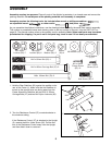
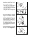
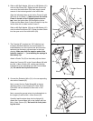
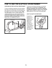
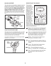
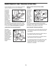
3. Lay a cloth over the front of the Frame (1) to protect it.
Lay the Upright (2) in the position shown. Connect the
Extension Wire (51) to the Reed Switch Wire (50).
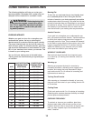
Next, connect the Resistance Cable (57) to the
Extension Cable (84) in the following way:
¥ Refer to drawing A. Pull up on the metal bracket, and
insert the tip of the Resistance Cable (57) into the
wire clip on the Extension Cable (84) as shown.
¥ Refer to drawing B. Firmly pull the Resistance Cable
(57) and slide it into the metal bracket on the
Extension Cable (84) as shown.
¥ Refer to drawing C. Using pliers, squeeze the prongs
on the upper end of the metal bracket together.
2
1
84
57
51
50
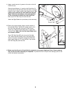
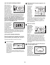
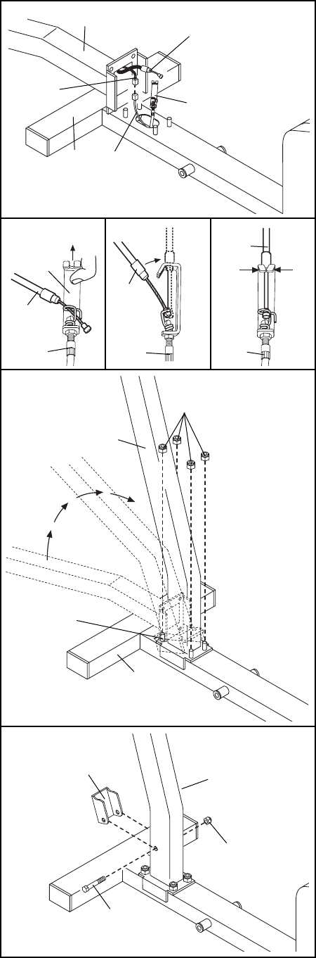
5. Attach the Incline Bracket (24) to the lower end of the
Upright (2) with the M10 x 85mm Bolt (25) and an M10
Nylon Locknut (26). Do not overtighten the Nylon
Locknut; the Incline Bracket must pivot easily.
24
25
26
2
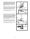
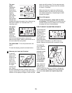
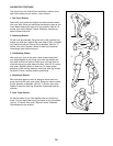
4. Align the two holes in the front of the Upright (2) with
the two welded bolts on the front of the Frame (1).
Carefully push the Reed Switch Wire (not shown) into
the Upright until there is no slack.
Next, pivot the Upright (2) about halfway to the vertical
position while guiding the metal bracket on the
Extension Cable (not shown) into the Upright. Once
the top edge of the metal beacket is inside the
Upright, pivot the Upright to the vertical position so it
rests on the four welded bolts on the Frame (1). Be
careful to avoid pinching the wires. Tighten a M10
Nylon Locknut (26) onto each welded bolt.
Refer to assembly step 2. Insert the tab on the Resis-
tance Control (57) into the Upright (2). Next, press the
bottom of the Resistance Control against the Upright.
Tighten the M4 x16mm Screw (35) into the Resistance
Control and the Upright.
2
1
Welded
Bolts
26
3