


11
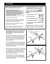
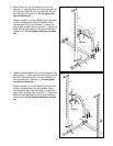
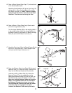
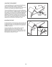
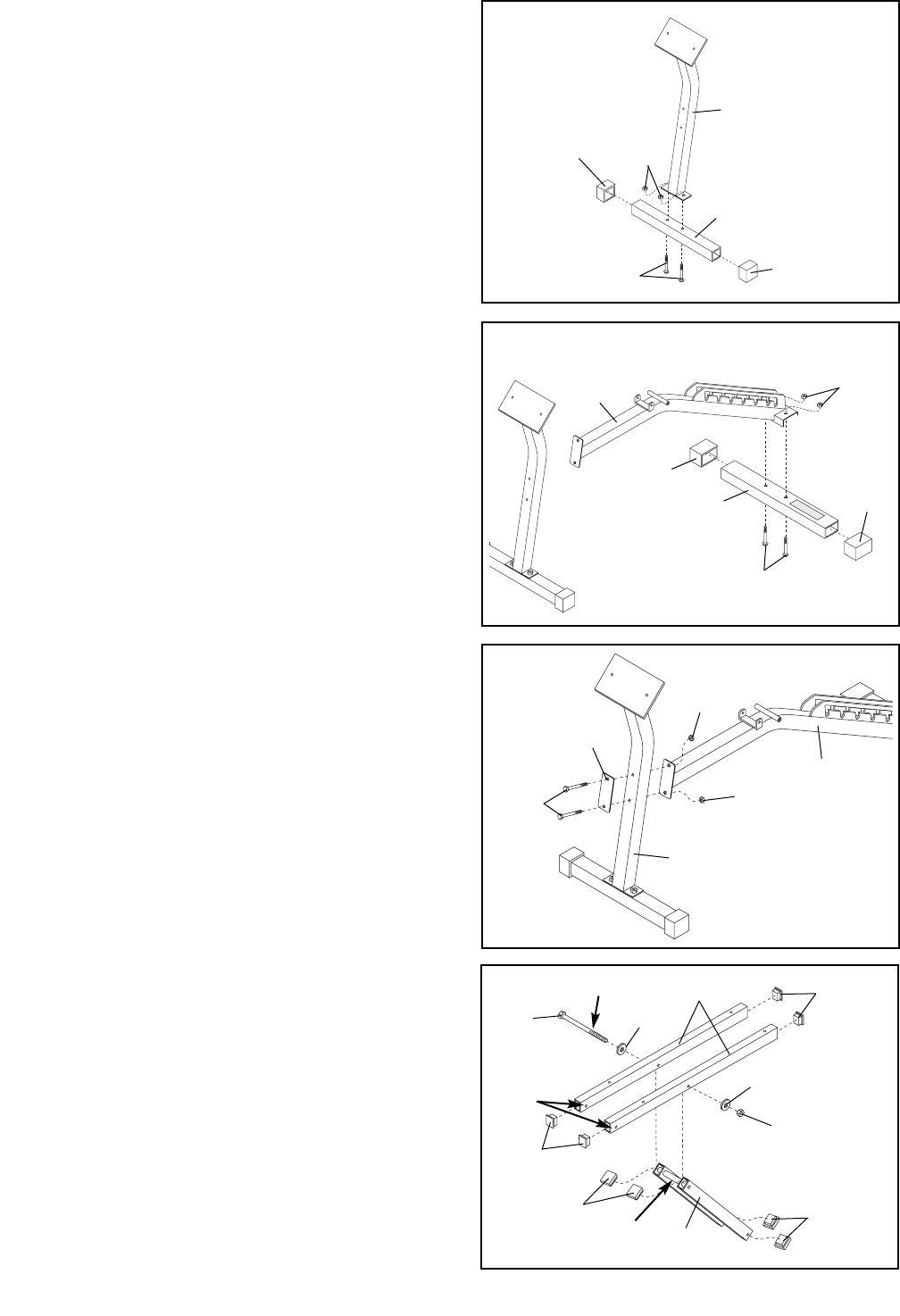
15. Press a 50mm Square Outer Cap (17) onto each end
of the Small Stabilizer (25).
Attach the Small Stabilizer (25) to the Front Leg (19)
with two M10 x 65mm Carriage Bolts (40) and two
M10 Nylon Locknuts (11). Note: There is an inden-
tation around the holes on one side of the Small
Stabilizer. This side must be facing the floor.
15
40
11
19
17
17
25
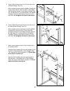
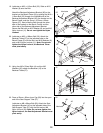
16. Press a 50mm x 70mm Outer Cap (10) onto each
end of the Large Stabilizer (26).
Turn the Large Stabilizer (26) so the warning decal is
in the position shown. Attach the Large Stabilizer to
the Bench Frame (5) with two M10 x 65mm Carriage
Bolts (40) and two M10 Nylon Locknuts (11).
16
40
5
10
11
10
26
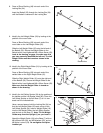
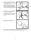
17. Attach the Front Leg (19) to the Bench Frame (5) with
two M10 x 70mm Bolts (46), a Small Support Plate
(16), and two M10 Nylon Locknuts (11).
17
19
11
11
5
16
46
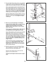
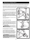
18. Press two 20mm x 40mm Inner Caps (28) into each
Backrest Tube (27). Press four 20mm x 40mm Inner
Caps into the Backrest Adjustment Bracket (36).
Lubricate an M10 x 180mm Bolt (22). Attach the
Backrest Tubes (27) to the welded tube on the
Backrest Adjustment Bracket (36) with the Bolt, two
M10 Washers (6), and an M10 Nylon Locknut (11).
Make sure that the Backrest Tubes are turned as
shown. The indicated holes are not centered in
the Backrest Tubes but are closer to one side.
Turn the Backrest Tubes so the holes are closer
to the floor. Do not over tighten the Nylon
Locknut; the Backrest Tubes must pivot easily.
18
28
28
6
11
36
Lubricate
6
Holes
Welded
Tube
28
28
22
27