


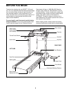
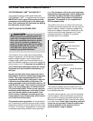
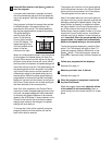

2. Identify the Right Upright (10), which has a large rectan-
gular hole near the upper end (see drawing 2b). Have a
second person hold the Right Upright near the Wire
Harness (17). Insert the end of the Wire Harness into the
Right Upright and out of the rectangular hole near the
upper end as shown. If necessary, use needlenose pliers
to pull the Wire Harness out of the hole.
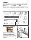
See drawing 2b. Locate the Left Upright (9). If the Latch
Housing (77) is not attached to the Left Upright, remove
the two Screws (76) from the Left Upright. Attach the
Latch Housing as shown with the two Screws. Firmly
tighten—but do not overtighten—the Screws.
2a
10
17
2b
17
77
76
9
10
Rectangular
Hole
Large
Hole
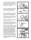
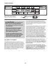
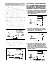
3. Make sure that the Right Upright (10) is turned so it
bends in the direction shown. Insert two 3” Bolts (47) with
Washers (29) through the Base (82) and
hand tighten
the Bolts into the lower end of the Right Upright.
With the help of a second person, tip the treadmill onto
its other side and repeat steps 1 through 3. Note: There
is not a wire harness in the Left Upright (not shown). An
extra Base Pad may be included.
47
29
82
Bend
10
3
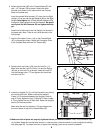
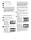
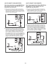
4. With the help of a second person, set the treadmill flat on
the floor so that the Right Upright (10) and the Left
Upright (not shown) are vertical.
Hold one of the Handrails (85) near the Right Upright
(10). Insert the end of the Wire Harness (17) into the bot-
tom of the Handrail and out of the indicated hole. Using the
Silver Screw (107), attach the end of the ground wire to
the small hole in the side of the Handrail.
10
85
17
107
4
Hole
Ground
Wire
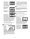
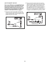
5. Have a second person hold the Console Base (87) and
the Handrail (85) in the position shown. Touch the Right
Upright (10) to discharge any static. Insert the Wire
Harness (17) through the two Plastic Ties (108) on the
Console Base. Find the 3-wire connector on the end of
the Wire Harness. Insert the connector into the red
socket beneath the Console Base. The connector
should slide easily into the socket and snap into
place. If the connector does not slide easily and snap
into place, turn the connector and then insert it. If the
connectors are not inserted properly, the Console
may be damaged when the power is turned on.
Insert the 5-wire connector into the black socket beneath
the Console in the same way. Make sure that the connec-
tors and wires appear as shown in the inset drawing. Insert
the excess Wire Harness (17) down through the Handrail.
Securely tighten the Plastic Ties (108) to prevent the
Wire Harness (17) from slipping. Then, cut off the ends
of the Plastic Ties.
17
87
85
10
5
108
7
5-wire
17
3-wire