


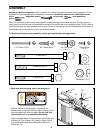
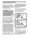
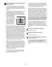
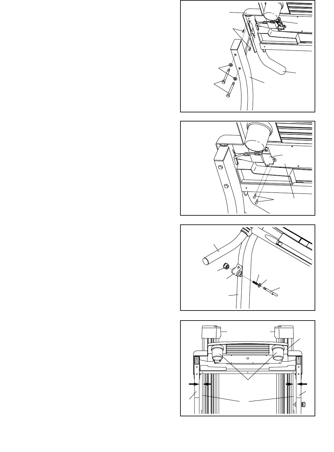
7. Hold the Connector Cover (110) on the Console Base
(87) in the position shown. Attach the Connector Cover
to the Console Base with two 3/4” Screws (68).
68
110
87
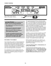
8. Remove the Latch Knob (105) from the Latch Pin (11).
Make sure that the Latch Pin Collar (14) and the Spring
(56) are on the Latch Pin as shown. Insert the Latch Pin
into the Storage Latch (77) and tighten the Latch Knob
onto the Latch Pin.
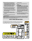
10.Make sure that all parts are properly tightened before you use the treadmill. Note: Extra hardware may
be included. Keep the included allen wrench in a secure place; the allen wrench is used to adjust the walking
belt (see page 23). To protect the floor or carpet from damage, place a mat under the treadmill.
77
9
85
14
56
11
8
7
105
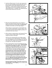
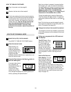
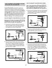
6. Attach the Handrail (85) to the Console Base (87) with
two 1 1/2” Screws (79) as shown. Attach the other
Handrail (not shown) to the other side of the Console
Base in the same way.
Insert the excess Wire Harness (17) down into the Right
Upright (10) as you set the right Handrail (85) on the Right
Upright. Hand tighten two 4” Bolts (89) with Washers (29)
through the Right Upright into the right Handrail. Be careful
not to pinch the Wire Harness. Do not tighten the Bolts
yet.
Attach the left Handrail to the Left Upright (not shown) in
the same way. Note: There is not a wire harness in the
Left Upright.
89
29
10
87
79
85
17
6
8
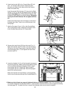
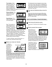
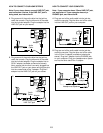
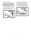
9. Lower the Uprights (9, 10) until the Handrails (not shown)
are touching the floor. Make sure that the treadmill Frame
(12) is centered between the Uprights. Refer to step 3.
Firmly tighten the four 3” Bolts (47). Refer to step 6.
Firmly tighten the four 4” Bolts (89). Raise the Uprights
back to the vertical position.
Make sure that the two Cup Holders (118) are pressed
into the round holes near the top of the Console Base (87).
9
10
Top View
9
12
87
118