


ENGLISH INSTRUCTIONS
IMPORTANT! WRITE MODEL NUMBER FROM BOX ONTO PAGE 1 OF THIS
OWNERS MANUAL
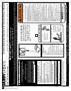
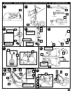
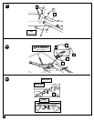
1. Remove all contents from tank (1).
2. Turn tank (1) bottom side up. Insert axle rod (2) through wheel (3), as shown.
Secure wheel assembly to tank by tapping wheel assembly downward with
hammer. It will snap into position. Repeat for opposite side, then carefully, turn
tank over.
3. Correctly identify each pole section and mark indicated distance from ends with
tape as shown.
4. IMPORTANT! Center alignment slot of middle pole section (4) in a lower hole
of top pole section (5) as shown. While maintaining alignment, bounce pole top
(5) and middle section (4) together as shown until they no longer move toward
taped reference mark. Upright assembly. NOTE: Pole sections should have a
3-1/2” (9 cm) minimum overlap.
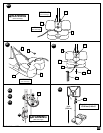
5. IMPORTANT! Center alignment slot of lower pole section (6) in a lower hole
of middle pole section (4) as in step 4. While maintaining alignment, bounce
assembly and lower section (6) together as shown until they no longer move
toward taped reference mark. NOTE: Pole sections should have a 3-1/2” (9 cm)
minimum overlap.
6. Install rod (7) through holes in bottom pole section (6) and eyebolt (8).
7. Insert pole assembly into tank assembly as shown.
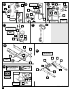
8. Carefully place unit on its side, and secure pole bottom (6) to tank as shown, a
deep socket is recommended. Upright unit. NOTE: Keep unnecessary pressure off
of the pole assembly when in this position. Two people recommended for this
procedure. IMPORTANT! Do not over tighten.
9. Secure tank struts (11) to pole. Rotate non-secured ends of tank struts (11)
outward to cups in tank as shown.
WARNING: TIGHTEN BOLT (12) IN LOCKNUT (14) UNTIL FLUSH (EVEN) WITH
LOCKNUT’S OUTER EDGE.
10. Secure non-secured ends of tank struts (11) to tank as shown.
Repeat for opposite side.
11. Install pole mount bracket (45), bracket reinforcement (54) with carriage bolts (46)
as shown. Tighten flange nuts (16) completely.
12. Attach spacers (47, 48) to pole mount bracket (45) with bolts (34), washers (49),
and nuts (25) as shown. IMPORTANT! Tighten until washers (49) no longer
move.
13. Attach covers (50) onto pole mount bracket (45) with carriage bolt (31) and nut (14)
as shown.
IMPORTANT: Loop end of pin lanyard (30) over carriage bolt (31) during this
assembly. NOTE: Assemble lanyard (30) to locking pin (27) as shown.
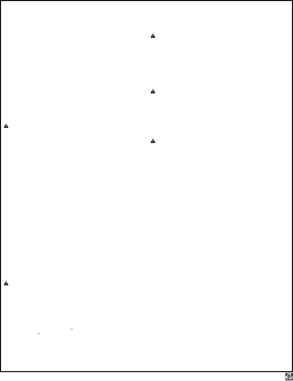
14. Apply logo and height indicator labels (44) to adjustment rod (43) as shown. Attach
handle parts (40, 41) to adjustment rod with screw (42), carriage bolt (22), and
flange nut (14) as shown. IMPORTANT: Indicator labels should be applied as
close to holes as possible to prevent labels from being damaged during
height adjustment.
NOTE: Holes in adjustment rod allow for either rear access or side access.
15. Insert handle assembly through pole mount assembly as shown. Lock pole
assembly in place at the 10’ (3.05 m) mark with pin (27).
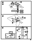
16. Install spacers (32) onto backboard brackets (18) with bolts (33, 34) and lock-nuts
(24, 25) as shown. NOTE: Test fit bolts into holes of brackets (18) and carefully
rock them in a circular motion to ream out paint from holes if necessary.
17. Install net clips (23) to rim (26).
The Quick Clip™ rapid release net system lets the net pull away from the rim. This
reduces the risk of player injury or property damage. However, improper
installation or a ball making contact at an odd angle may disengage the net clip
from the goal rim. Usually, the clip is reinstalled with little or no problem. We hope
that you agree this inconvenience is minor when compared to the safety of the
players. Quick Clip: US Patent No. 5,792,010/5,795,253
The two outer hooks on net clip must face towards inside of goal rim. Insert larger
hole in net clip onto rim stud, push down on net clip, then slide net clip right,
locking or snapping securely into position (clips must "snap" into place to insure a
secure fit). NOTE: Net clips should not slide with ease. It is very important that
the net clips are in the locked position before going on to next step.
WARNING: USE OF THIS PRODUCT WITHOUT PROPER INSTALLATION OF
NET CLIPS, OR WHEN ALL NET CLIPS ARE NOT PRESENT COULD RESULT
IN BODILY HARM. BE SURE TO FOLLOW DIRECTIONS CAREFULLY.
18. Assemble lower elevator tubes (35) and springs (51) as shown. Tighten
completely.
IMPORTANT! It is necessary for all parts to be installed for this mechanism
to work safely and properly.
19. Bend bracket (18) to line up with holes in backboard.
20. Starting with nuts (16) flush against bracket (18), secure rim (26) and bracket to
backboard. IMPORTANT! For spring loaded rim assembly, refer to instructions
included with rim hardware. NOTE A
: Do not use washers here on spring return
style rim. NOTE B
: Mounting nuts and bolts supplied with rim hardware.
21. Assemble upper elevator tubes (39) to backboard brackets (18).
22. Support pole on sawhorse. Attach backboard assembly to top pole section (5).
Then install pole cap (29). NOTE: Two people are recommended for this step. Use
caution; elevator assembly is heavy.
23. Install handle assembly to lower elevator tubes (35) using bolt (36), spacers (38),
and nut (37) as shown. NOTE: Before going on to next step, set adjustment
system assembly to the 10’ (3.05 m) setting.
24. Insert bolt (36) through left side upper elevator tube (39), then stretch spring (51)
onto bolt (36). Insert bolt (36) through right side upper elevator tube (39) and
secure with nut (37).
WARNING: USE EYE PROTECTION WHEN INSTALLING SPRINGS.
25. Install net (52) as shown. IMPORTANT! Make sure net is held by all three
hooks on the net clip.
NOTE: Stretching net up then pulling side to side will help snap net under center
hook.
26. Loosely install hardware (58 and 59) into holes as shown in Figure B. Attach board
pads (55, 56, 57) onto hardware and tighten completely. NOTE: Do NOT
overtighten.
27. NOTE: Two people recommended for this procedure.
Carefully upright assembly. Place assembled unit in desired location. Bend Wide
Body (54) tank up and fill lower tank with water (30 gal., 114 liters or sand, 250
lbs., 113 kgs.) and snap tank cap (17) into place.
WARNING: DO NOT LEAVE ASSEMBLY UNATTENDED WHEN EMPTY.
SYSTEM MAY TIP OVER.
IMPORTANT! Add two gallons (7.6 liters) of NON-TOXIC ANTIFREEZE in sub-
freezing climates.
28. Fill upper tank with water (10 gal., 38 liters or sand 100 lbs., 45 kgs.). Snap tank
caps (17) into place. IMPORTANT! Add one gallon (3.8 liters) of NON-TOXIC
ANTIFREEZE in sub-freezing climates.
29. Secure assembly to ground using rope (20), ground stake (19), bolt (15) and nut
(16) as shown.
30. While holding handle, remove pin (27).
WARNING: DO NOT ALLOW CHILDREN TO ADJUST HEIGHT.
31. Move elevator up or down to desired height.
32. Replace pin (27) full length to lock system at desired height.
33. Apply height and transport label (21) to front of pole as shown. Regulation rim
height is 10 feet (3.05m).
4
P/N 211343 10/00
printed on recycled paper