


3
P/N 211636A 05/03
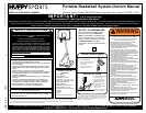
ENGLISH INSTRUCTIONS
IMPORTANT! WRITE DOWN MODEL NUMBER FROM BOX ON
PAGE 1 OF THIS OWNERS MANUAL
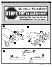
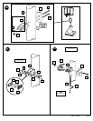
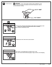
1.
Insert axle (2) into tank (1) as shown to secure wheel (3) and
eyebolt (57) into position. Repeat procedure for opposite side.
2.
Position front cover (47) on top of tank (1) as shown, insert eye
bolts (57) through cover, snapping front cover over axles (2) at
the same time. Tighten completely.
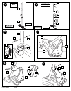
3. Mark pole sections with tape as shown.
4. Bounce top pole section (4) and middle section (5) together as
shown until they no longer move toward taped reference mark.
Upright assembly. NOTE: Pole sections should have a 3-1/2”
(9 cm) overlap minimum.
5. IMPORTANT! Holes in top (4) and bottom pole (6) sections
must align to correctly position elevator system toward
playing surface. Add bottom pole section (6) to assembly as
shown and bounce until they no longer move toward taped
reference mark. NOTE: Pole sections should have a 3 1/2”
(9 cm) overlap minimum.
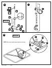
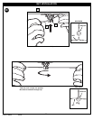
6. Insert bolts (7) into bracket (9) as shown. Install bolt (14)
through bracket (9) and bottom pole section (6) and secure with
nut (12) as shown.
7. Carefully tip unit forward and secure pole assembly to tank (1)
with washers (13) and nuts (16) as shown.
8. Install rod (11) through bottom pole section (6) as shown. Install
eye bolts (8) onto rod (11) as shown.
9. Secure cover (47) to rod (11) using washers (55) nuts (10) and
bolt covers (15) as shown.
10. Install pole mount bracket (17) and reinforcement bracket (58)
with carriage bolts (18) as shown. Tighten flange nuts (16)
completely.
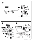
11. Attach spacers (22, 23) to pole mount bracket (17) with bolts
(21), washers (19), and nuts (20) as shown. IMPORTANT!
Tighten just until washers (19) stop moving.
12. Attach covers (24) onto pole mount bracket (17) with carriage
bolt (25) and nut (16) as shown. IMPORTANT! Loop end of
pin lanyard (27) over carriage bolt (25) during this assembly.
NOTE: Assemble lanyard (27) to locking pin (26) as shown.
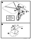
13. Apply logo and height indicator labels (29) to adjustment rod (28)
as shown. Attach handle parts (32, 33) to adjustment rod with
screw (31), carriage bolts (30), and flange nuts (16) as shown.
IMPORTANT! Indicator labels should be applied as close to
holes as possible to prevent labels from being damaged
during height adjustment.
14. Insert handle assembly through pole mount assembly as shown.
Lock pole assembly in place at the 10’ (3.05 m) mark with pin
(26).
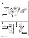
15. Attach backboard support brackets (35) to the backboard frame
using bolts (21), spacers (36), washers (55) and nuts (20) as
shown.
16. Attach lower elevator tubes (40) and counter balance spring (41)
to backboard support brackets (35) using spacers (34), bolt (37),
and nut (39) as shown. NOTE: Rim mounting nuts and bolts
(56) supplied with rim hardware. NOTE: DO NOT use washers
here on spring return style rims.
17. Install cover (60) over spring return mechanism as shown.
18. Attach upper elevator tubes (43) to backboard support brackets
(35) using spacers (34), bolt (58), and nut (39) as shown.
19. Install net clips (50) to rim (42). See Illustration.
20. Install net (51). See Illustration.
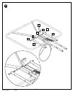
21. Support pole on sawhorse. Attach backboard assembly to top
pole section (4) as shown. Install pole cap (46). NOTE: Two
people are recommended for this step. Use caution; elevator
assembly is heavy.
22. Install upper elevator tubes (43) to triangle plates (45) as shown.
Install handle assembly to lower elevator tubes (40) using bolt
(37), spacers (44), and nut (39) as shown. NOTE: Before going
on to next step, set adjustable system assembly to the 10’ (3.05
m) setting.
23. Insert bolt (37) through left side upper elevator tube (43), then
stretch spring (41) onto bolt (37). Insert bolt (37) through right
side upper elevator tube (43) and secure with nut (39).
WARNING: USE EYE PROTECTION WHEN INSTALLING
SPRINGS.
24. Roll completed assembly to desired position. Fill tank with water
(approx. 34 gallons (129 Liters)) or sand (approx. 280 lbs. (128
kg)) and snap cap (49) in place. Secure assembly to ground
using rope (52) and tie down stake (53).
IMPORTANT! Add two gallons (7.6 Liters) of non-toxic
antifreeze in sub-freezing climates.
WARNING: DO NOT LEAVE ASSEMBLY UNATTENDED
WHEN EMPTY, MAY TIP OVER.
25. Apply height adjustment and moving label (54) to front of pole as
shown.
WARNING: DO NOT ALLOW CHILDREN TO ADJUST
HEIGHT.
26. While holding handle, remove pin (26).
27. Move elevator up or down to desired height.
28. Replace pin (26) full length to lock system at desired height.