


09/02 P/N 211455C
3
ENGLISH INSTRUCTIONS
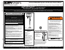
IMPORTANT! WRITE MODEL NUMBER FROM BOX ONTO PAGE 1 OF THIS OWNERS
MANUAL
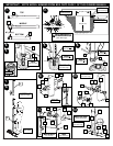
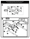
1. Mark middle and bottom pole sections indicated distance from ends with tape.
2. WARNING: CONTACT UTILITIES BEFORE DIGGING.
Ensure ground is level with playing surface, then dig pole hole. NOTE: Maximum distance from
edge of hole to edge of playing surface 6” (15.2 cm).
WARNING: THIS HOLE SIZE REPRESENTS THE MINIMUM REQUIREMENT FOR IDEAL
CONDITIONS. THE LOCATION (HILL/INCLINE) OF THE POLE, SOIL CONDITIONS
(SAND/CLAY) AND OTHER FACTORS COULD REQUIRE A LARGER HOLE SIZE AND
CONCRETE FOOTING.
3. Insert and secure bottom pole section into ground sleeve (4).
4. Fill hole approximately 1/3 full with concrete. Insert ground sleeve assembly and center in hole.
Fill hole completely with concrete.
NOTE: Make sure that bottom of ground sleeve flange is level with playing surface.
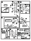
5. Tamp down concrete to release air pockets and build drainage hill. Level pole section in all
directions several times while concrete is curing. NOTE A
: Mark here for tape. NOTE B: Keep
flange pushed down to concrete and leveled. IMPORTANT! Wait a minimum of 24 hours
before going on to next step. Concrete must cure.
6. After concrete has cured, remove bottom pole section from ground sleeve (4). Place anti-skid
tape (6) around bottom of pole. NOTE A
: Place top edge of tape on mark. NOTE B: Tape
prevents the pole from rotating during play.
7. Install ground sleeve cap (5) onto bottom pole section. Stack and bounce bottom and middle pole
sections together. Bounce pole sections together until middle section no longer moves toward
taped reference mark.
8. Stack upper pole section (1) to bottom pole assembly and continue bouncing until poles no
longer move toward taped reference marks. IMPORTANT! Pole sections should have a 3-3/4”
(9.5CM) minimum overlap.
9. Install pole mount bracket (7), bracket reinforcement (44) with carriage bolts (8) as shown.
Tighten flange nuts (9) completely.
10. Attach spacers (10, 11) to pole mount bracket (7) with bolts (12), washers (13), and nuts (14) as
shown. IMPORTANT! Tighten until washers (13) no longer move.
11. Attach covers (15) onto pole mount bracket (7) with carriage bolt (16) and nut (9) as shown.
IMPORTANT: Loop end of pin lanyard (18) over carriage bolt (16) during this assembly.
NOTE: Assemble lanyard (17) to locking pin (18) as shown.
12. Apply logo and height indicator labels (19) to adjustment rod (20) as shown. Attach handle parts
(21, 22) to adjustment rod with screw (23), carriage bolt (24), and flange nut (9) as shown.
IMPORTANT! Indicator labels should be applied as close to holes as possible (as shown in
illustration) to prevent labels from being damaged during height adjustment. NOTE: Holes
in adjustment rod allow for either rear access or side access.
13. Insert handle assembly through pole mount assembly as shown. Lock pole assembly in place at
the 10’ (3.05 m) mark with pin (18).
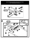
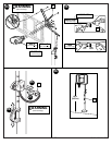
14. Install spacers (25) onto backboard brackets (26) with bolts (12, 27) and lock-nuts (14, 28) as
shown. IMPORTANT! Test fit bolts (12, 27) into holes of brackets (26) and carefully rock
them in a circular motion to ream out paint from holes if necessary.
15. Assemble elevator tubes (30) as shown. Tighten completely. Bend bracket (26) to line up with
holes in backboard. IMPORTANT! It is necessary for all parts to be installed for this
mechanism to work safely and properly.
14. Install spacers (25), and springs (39) onto backboard brackets (26) with bolts (27, 36), washers
(37) and lock-nuts (14, 28) as shown. IMPORTANT! Test fit bolts into holes of brackets (25)
and carefully rock them in a circular motion to ream out paint from holes if necessary.
15. Assemble elevator tubes (30) as shown. Tighten completely. Bend bracket (26) to line up with
holes in backboard. IMPORTANT! It is necessary for all parts to be installed for this
mechanism to work safely and properly.
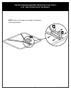
16. Support pole on sawhorse. Attach backboard assembly to top pole section (1). NOTE: Two
people are recommended for this step, use caution, elevator assembly is heavy.
17. Install handle assembly to long elevator tubes (30) using bolt (31), spacers (33), and nut (35) as
shown. NOTE: Before going on to next step, adjust adjustable system assembly to the 10’
setting.
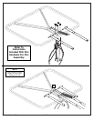
18. Insert bolt (31) through left side short elevator tube (29), then stretch spring (34) onto bolt (31).
Insert bolt (31) through right side short elevator tube (29) and secure with nut (35).
WARNING: USE EYE PROTECTION WHEN INSTALLING SPRINGS.
19. Secure pole end with tape (not included). NOTE: Make sure that concrete does not bulge from
the end of pole assembly. Fill pole with concrete approximately 1” (2.54 cm) below bottom hole
as shown. Allow concrete to completely cure. IMPORTANT! Failure to fill your pole
completely with concrete as described in these instructions will void all warranties written
and implied. IMPORTANT! Wait a minimum of 24 hours before going on to next step.
Concrete must cure.
20. Remove tape, install pole cap (40), fit pole assembly into sleeve (4).
IMPORTANT! Position pole section so the elevator assembly is perpendicular with playing
surface. IMPORTANT! The elevator holes MUST be parallel with playing surface.
WARNING: TWO PEOPLE ARE RECOMMENDED FOR THIS STEP. POLE FILLED WITH
CONCRETE WEIGHS APPROXIMATELY 125 LBS. (56.7 KG). USE PROPER PRECAUTION.
21. Use wedge to tap cap of ground sleeve until tight.
22. Install net clips (42).
The Quick Clip™ rapid release net system lets the net pull away from the rim. This reduces the
risk of player injury or property damage. However, improper installation or a ball making contact
at an odd angle may disengage the net clip from the goal rim. Usually, the clip is reinstalled with
little or no problem. We hope that you agree this inconvenience is minor when compared to the
safety of the players. Quick Clip: US Patent No. 5,792,010/5,795,253.
The two outer hooks on net clip must face towards inside of goal rim. Insert larger hole in net clip
onto rim stud, push down on net clip, then slide net clip right, locking or snapping securely into
position (clips must "snap" into place to insure a secure fit). NOTE: Net clips should not slide
with ease. It is very important that the net clips are in the locked position before going on to next
step.
WARNING: USE OF THIS PRODUCT WITHOUT PROPER INSTALLATION OF NET CLIPS, OR
WHEN ALLNET CLIPS ARE NOT PRESENT COULD RESULT IN BODILY HARM. BE SURE
TO FOLLOW DIRECTIONS CAREFULLY.
23. Starting with nuts flush against bracket, secure rim and bracket to backboard.
IMPORTANT! For spring loaded rim assembly, refer to instructions included with rim
hardware.
NOTE A
: Do not use washers here on spring return style rim.
NOTE B: Mounting nuts and bolts supplied with rim hardware.
WARNING: TWO PEOPLE ARE NECESSARY TO MOUNT THE BACKBOARD ASSEMBLY TO
THE POLE. ONE PERSON SHOULD NOT ATTEMPT TO DO THIS ALONE.
WARNING: MOUNTING THE BACKBOARD ASSEMBLY TO THE POLE IS PERFORMED AT
AN ELEVATED HEIGHT.USE PROPER PRECAUTION.
24. Install net (43) as shown.
IMPORTANT! Make sure net is held by all three hooks on the net clip.
NOTE: Stretching net up then pulling side to side will help snap net under center hook.
25. While holding handle, remove pin (18).
WARNING: DO NOT ALLOW CHILDREN TO ADJUST HEIGHT.
26. Move elevator up or down to desired height.
27. Replace pin (18) full length to lock system at desired height.
28. Apply height adjustment label (38) to front of pole as shown.
Regulation rim height is 10 feet (3.05 m).
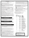
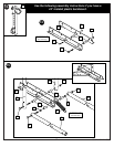
Use the following assembly instructions if you have a
48” MOLDED PLASTIC-FRAMED ACRYLIC BACKBOARD
Use the following assembly instructions if you have a
48” MOLDED PLASTIC BACKBOARD
Use the following assembly instructions if you have a
44” MOLDED PLASTIC BACKBOARD
WARRANTY CARD:
Please remember to complete your product reg-
istration form either
on-line at: www.huffysports.com/warrantycard
or mail-in the enclosed postcard.
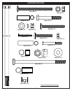
PARTS LIST
See Hardware Identifier
Item
Qty. Part No. Description
1 1 914822 Top Pole Section
2 1 908407 Middle Pole Section
3 1 908812 Bottom Pole Section
4 1 202800 Ground Sleeve
5 1 202801 Ground Sleeve Cap
6 1 203279 Anti-Skid Tape
7 1 204832 Bracket, Pole Mount
8 2 203053 Bolt, Carriage, 5/16-18 x 4 long
9 5 203100 Nut, Hex-Flange, 5/16-18
10 2 204857 Spacer, 1/2 O.D. x 1.44 long
11 2 204858 Spacer, Biscuit
12 3 206360 Bolt, Hex-Head, 3/8-16 x 2.625 long
13 4 203232 Washer, 3/8 x 3/4 O.D.
14 3 201124 Nut, Hex-Centerlock, 3/8-16
15 2 204859 Cover, Plastic (Black)
16 1 203038 Bolt, Carriage, 5/16-18 x 2.75 long
17 1 204853 Lanyard, Plastic Coil (Black)
18 1 204850 Pin, Height Adjustment
19 1 204872 Label, Logo/Height Indicator
20 1 904866 Height Adjustment Rod
21 1 204855 Handle, Left Plastic (Black)
22 1 204856 Handle, Right Plastic (Black)
23 1 204803 Screw, Phillips-Head, 1.5 long
24 2 203103 Bolt, Carriage, 5/16-18 x 2 long
25 4 201129 Spacer, 1.8 long x .402 I.D. x .5 O.D.
26 2 900846 Backboard Bracket (Black)
27 1 240017 Bolt, Hex-Head, 1/4-20 x 2 1/4 long
28 1 203493 Nut, Hex, 1/4-20, Centerlock
29 2 904807 Upper Elevator Tube (Black), short
30 2 904821 Lower Elevator Tube (Black), long
31 6 204847 Bolt, Hex-Head, 1/2-13 x 9.5 long
32 2 206311 Spacer, .53 I.D. x .65 O.D. x .5 long
33 12 202862 Spacer, .563 I.D. x .68 O.D. x 1.19 long
34 2 204837 Spring, Counterweight, Black
35 6 206340 Locknut, Hex Centerlock, 1/2-13
36 1 202789 Bolt, Hex Head, 3/8-16 x 6 long
37 2 203309 Washer, .406 I.D. x 1.0 O.D.
38 1 201251 Label, Height Adjustment
39 2 204838 Spring, Counterweight, Zinc Plated
40 1 207103 Pole Cap
41 1 Rim, (Black)
1 Rim, (Red)
42 12* 200120 Clip, Net Holder, (Red)
12* 200121 Clip, Net Holder, (Black)
43 1 Net
44 1 206990 Bracket Reinforcement
* You may have extra parts with this model.