


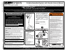

INSTRUCTIONS
IMPORTANT! WRITE DOWN MODEL NUMBER FROM BOX ON PAGE 1
OF THIS OWNERS MANUAL
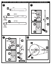
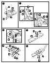
1. Install wheel axle (2) through wheel carriage (68) and install wheels (3)
onto wheel axle (2) with spacers (67) as shown. Secure wheel bracket
as shown, a deep socket is recommended.
IMPORTANT! DO NOT OVER TIGHTEN.
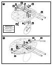
2. Correctly identify each pole section and mark indicated distance from
ends with tape as shown.
3. IMPORTANT! Holes in top (4) and middle pole (5) sections MUST
align to correctly position elevator system toward playing surface.
IMPORTANT! Bounce pole top (4) and middle section (5) together
as shown until they no longer move toward taped reference mark.
Upright assembly. NOTE: Pole sections should have a 3-1/2" (9 cm)
minimum overlap.
4. IMPORTANT! Holes in top (4) and bottom pole (6) sections MUST
align to correctly position elevator system toward playing surface.
Add bottom pole section (3) to assembly as shown and bounce until
completely tight. NOTE: Pole sections should have a 3-1/2" (9 cm)
minimum overlap. Once assembled, pole sections CAN NOT be
separated!
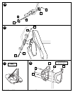
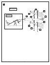
5. Install rod (7) through holes in bottom pole section (6) and eyebolt (8).
6. Insert pole assembly into tank assembly as shown. Secure pole
assembly with upper pivot bracket (9) and lock nut (10).
7. Secure base struts (11) to pole using bolt (12,) washers (13), and nut
(14), as shown.
WARNING: TIGHTEN BOLT (12) IN LOCK NUT (14) UNTIL FLUSH
(EVEN) WITH LOCK NUT’S OUTER EDGE.
Rotate the non-secured ends of base struts (11) as shown.
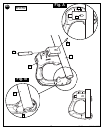
8. Secure base struts (11) to base using bolt (16) washers (13)
and nut (17).
9. Insert carriage bolts (18) into middle set of holes on wheel bracket (19)
as shown.
10. Attach lower pivot bracket (20) to wheel bracket using bolt (21), washers
(13), disc (22), and nut (10) as shown.
11. Attach handle bar (23) to wheel bracket assembly using nuts (17) as
shown.
12. Install wheels (3) onto axle (24) and wheel bracket assembly with push
caps (25) as shown.
13. Attach wheel bracket assembly to base assembly using bolt (26),
washers (13), and nut (10) as shown.
14. Carefully reposition entire assembly as shown.
NOTE: Two people recommended for this step.
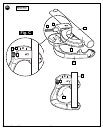
15. Attach front of plastic handle (27) to back of plastic handle (28) around
handle bar (23) using self- tapping screws (29) as shown.
IMPORTANT! Front of plastic handle (27) should face outward, away
from pole assembly.
16. Insert bolts (30) through plastic handle assembly, handle bar (23), and
attach nuts (17) as shown. Tighten completely.
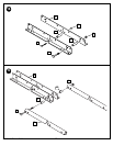
17. Attach elevator bracket (38) to middle pole section (5) using bolts (39)
and nuts (17) as shown.
18. Assemble board brackets (40) using spacers (44) bolts (45, 46) and nuts
(47, 48) as shown.
19. Attach lower elevator tubes (52) to backboard brackets (40) using
spacers (49) bolt (51) and nut (50) as shown.
20. Bend top of backboard brackets (40) outward to match up with holes on
the backboard and secure using nuts (17) and bolts (43) as shown.
Attach rim (32) to backboard using using bolts (42) and nuts (17) as
shown.
NOTE: DO NOT use washers here on spring return style rims.
21. Attach upper elevator tubes (55) to backboard brackets (40) using
spacers (53) bolt (54) and nut (50) as shown.
22. Attach upper and lower elevator tubes (55, 52) to upper pole section (4)
using bolts (51, 54) spacers (67) and nuts (50) as shown. Attach pole
cap (33) as shown.
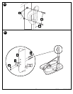
23. Insert locking pin (57) into bracket on adjustment rod (60). Insert cross
pin (56) through hole in bracket and locking pin (57) as shown in figure A.
Fit left handle (58) onto adjustment rod (60) so that the bottom of
adjustment rod (60) sits on the two small ribs as shown in figure B.
24. Insert spring (61) into back of locking pin (57) as shown. Spring (61)
should rest between two small ribs on back of plastic handle as shown in
Figure C. Insert top of trigger (66) into bracket on adjustment rod (60)
as shown. Plastic post on handle pieces should go through hole in
bottom of trigger (66) and hold it into place as shown.
25. Finish handle assembly by attaching right handle (59) using screws (29)
as shown.
26. Attach adjustment rod (60) to lower elevator tubes (52) using bolt (51)
spacers (62) and nut (50) as shown.
27. Insert lower adjustment tube (63) into bottom of adjustment rod (60), pull
trigger to allow lower adjustment tube to move about mid-way into
adjustment rod (60), release trigger so that lower adjustment tube (63)
locks into position midway inside adjustment rod (60). Attach lower
adjustment tube (63) to elevator bracket (38) using bolt (64) and nut (14)
as shown.
WARNING: TWO PERSON MINIMUM REQUIRED FOR THIS
PROCEDURE. NOT FOLLOWING RECOMMENDATION MAY
RESULT IN BODILY INJURY.
WARNING: DO NOT LEAVE ASSEMBLED UNIT UNATTENDED
WHEN EMPTY, MAY TIP OVER.
28. Roll completed assembly to desired playing area. Secure assembly to
ground using T-Strap (15) and tie down stake (34). Fill tank with 30
gallons of water.
IMPORTANT! Add two gallons (7.6 Liters) of non-toxic antifreeze in
sub-freezing climates.
WARNING: DO NOT LEAVE ASSEMBLY UNATTENDED WHEN
EMPTY, MAY TIP OVER.
29. Apply height adjustment and moving label (36) to front of pole as shown.
30. Lock elevator system into highest position (so that backboard is as high
as it will go). Apply 10 ft. height indication sticker (65) to adjustment tube
(63) directly below arrow on handle as shown. Move elevator system to
the next position and apply the 91/2 ft. sticker. Repeat until all height
settings have been labeled (8-10ft.).
31. Pull trigger (66). Move elevator system up or down to desired height,
release trigger (66) to lock system into one of the five height settings.
WARNING: DO NOT ALLOW CHILDREN TO ADJUST HEIGHT.
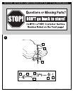
WARNING: USE OF THIS PRODUCT WITHOUT PROPER
INSTALLATION OF SMART CLIPS, OR WHEN ALL SMART CLIPS
ARE NOT PRESENT COULD RESULT IN BODILY HARM. BE SURE
TO FOLLOW DIRECTIONS CAREFULLY.
32. Install net clips as shown. (See illustration)
33. Install net as shown. (See illustration)
6
P/N 214945B 05/03
WARRANTY CARD:
Please remember to complete your product
registration form either on-line at:
www.huffysports.com/warrantycard or mail-in
the enclosed postcard.