


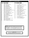

6
P/N 214946C 05/03
INSTRUCTIONS
IMPORTANT! WRITE MODEL NUMBER FROM BOX ONTO PAGE 1 OF
THIS OWNERS MANUAL
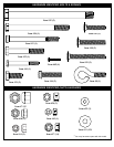
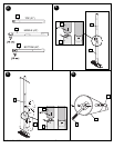
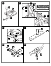
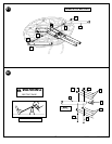
1. Remove all contents from underside of tank. Install wheel axle (2) through
wheel carriage (54) and install wheels (3) onto wheel axle (2) with spacers
(55) as shown. Secure wheel bracket as shown, a deep socket is
recommended.
IMPORTANT! DO NOT OVER TIGHTEN.
2. Correctly identify each pole section and mark indicated distance from ends
with tape as shown.
3. Align pole top and middle pole sections as shown using alignment mark
and hole.
IMPORTANT! Holes in top (4) and middle pole (5) sections MUST
align to correctly position elevator system toward playing surface.
Bounce pole top (4) and middle section (5) together as shown until they
no longer move toward taped reference mark. NOTE: Pole sections
should have a 3-1/2" (9 cm) minimum overlap.
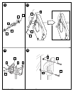
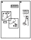
4. IMPORTANT! Holes in top (4) and bottom pole (6) sections MUST
align to correctly position elevator system toward playing surface.
Add bottom pole section (6) to assembly as shown using alignment mark
and hole, and bounce until completely tight. Once assembled, pole
sections CAN NOT be separated! NOTE: Pole sections should have a
3-1/2" (9 cm) minimum overlap.
5. Install rod (7) through holes in bottom pole section (6) and eyebolt (8).
6. Insert pole assembly into tank assembly as shown. Secure pole assembly
with upper pivot bracket (9) and lock nut (10).
7. Secure base struts (11) to pole using bolt (12), washers (13), and nut (14),
as shown. Place vinyl bolt cover (36) over exposed bolt threads. Rotate
the non-secured ends of base struts (11) as shown.
8. Secure base struts (11) to base using bolt (16), washers (13), and
nut (17).
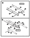
9. Insert carriage bolts (18) into middle set of holes on wheel bracket (19) as
shown.
10. Attach lower pivot bracket (20) to wheel bracket (19) using bolt (21),
washers (13), disc (22), and nut (10) as shown.
11. Attach handle bar (23) to wheel bracket assembly using nuts (17) as
shown.
12. Install wheels (3) onto axle (24) and wheel bracket assembly with push
caps (25) as shown.
13. Attach wheel bracket assembly to base assembly using bolt (26), washers
(13), and nut (10) as shown.
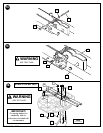
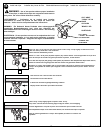
14. NOTE: Two people recommended for this step. Carefully reposition
entire assembly to upright position.
Attach front of plastic handle (27) to back of plastic handle (28) around
handle bar (23) using self-tapping screws (45) as shown.
IMPORTANT! Front of plastic handle (27) should face outward, away
from pole assembly.
15. Insert bolts (30) through plastic handle assembly, handle bar (23) and
attach nuts (17) as shown. Tighten completely.
16. IMPORTANT! Test fit bolts into holes of backboard brackets (38) and
carefully rock them in a circular motion to ream out paint from holes
if necessary.
Fit spacer (39) into pawl (40). Then continue to assemble as shown.
Tighten completely.
17. Assemble elevator tubes (43) to ratchet components as shown. Tighten
completely. IMPORTANT! It is necessary for all parts to be installed
properly for this mechanism to work safely and properly.
18. Secure pawl (40) in place with clevis pin (48).
19. Stretch spring (56) into position with pliers.
WARNING: USE EYE PROTECTION WHEN INSTALLING
SPRINGS.
20. WARNING: TWO PERSON MINIMUM REQUIRED FOR THIS
PROCEDURE. NOT FOLLOWING RECOMMENDATION MAY RESULT
IN BODILY INJURY.
Starting with nuts (17) flush against backboard bracket (38), secure rim
and bracket to backboard. Bend upper halves of backboard brackets to
line up with holes in backboard and secure. Tighten completely. NOTE:
Mounting nuts and bolts supplied with rim hardware.
21. Assemble elevator tubes (43) to backboard bracket as shown.
22. WARNING: TWO PERSON MINIMUM REQUIRED FOR THIS
PROCEDURE. NOT FOLLOWING RECOMMENDATION MAY RESULT
IN BODILY INJURY.
Support pole on sawhorse. Attach backboard assembly to top pole section
(4) as shown.
Then install pole cap (37). NOTE: Two people are recommended for this
step, use caution, elevator assembly is heavy.
23. WARNING: DO NOT LEAVE ASSEMBLED UNIT UNATTENDED
WHEN EMPTY, MAY TIP OVER.
NOTE: Two people recommended for this procedure. Roll the completed
assembly to the desired playing area. Insert the T-strap (15) through the
slot on the back of the base as shown. Secure the unit to ground by
twisting the tie down stake (49) into the ground and hooking the T-strap
(15) onto the tie down stake (49). Fill tank with 33 gallons of water.
IMPORTANT! Add 2 gallons (7.6 liters) of non-toxic antifreeze in
sub-freezing climates.
24. Apply height adjustment and moving label (51) to front of pole as shown.
Regulation rim height is 10 feet (3.05 m).
WARNING: DO NOT ALLOW CHILDREN TO ADJUST HEIGHT.
WARNING: USE OF THIS PRODUCT WITHOUT PROPER
INSTALLATION OF SMART CLIPS, OR WHEN ALL SMART CLIPS
ARE NOT PRESENT COULD RESULT IN BODILY HARM. BE SURE TO
FOLLOW DIRECTIONS CAREFULLY.
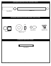
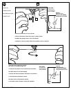
25. Install net clips as shown. (See illustration)
26. Install net as shown. (See illustration)