


5
06/03 P/N 211972B
INSTRUCTIONS
IMPORTANT! WRITE MODEL NUMBER FROM BOX ONTO PAGE 1 OF THIS
OWNERS MANUAL
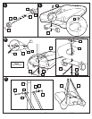
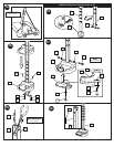
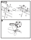
1. Mark pole sections with tape as shown.
2. IMPORTANT! Bounce pole top (1) and middle section (2) together as
shown until they no longer move toward taped reference mark.
Upright assembly. NOTE: Pole sections should have a 3-1/2" (9 cm)
minimum overlap.
3. IMPORTANT! Holes in top (1) and bottom pole (3) sections MUST
align to correctly position elevator system toward playing surface.
Add bottom pole section (3) to assembly as shown and bounce until
completely tight. NOTE: Pole sections should have a 3-1/2" (9 cm)
minimum overlap.
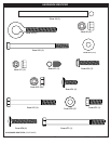
4. Install wheels (17) onto axle (28) and wheel bracket (25) with push caps
(29) as shown.
5. Position base as shown. Secure wheel bracket assembly with bolt (16) and
nut (15) as shown.
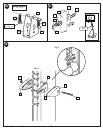
6. Install rod (4) through holes in bottom pole section (3) and eyebolt (5).
Insert pole assembly into tank (6) and through center hole on wheel
assembly as shown. Secure pole assembly with strap (61), washer (11)
and lock nut (8).
7. Secure base struts (9) to pole using bolt (10) washers (11) and nut (12) as
shown. Rotate the non-secured ends of base struts (9) as shown.
8. Secure base struts (9) to base using bolt (14) washers (11) and nut (15).
9. Install upper pivot bracket (18) to front of base using bolt (19), washer (20)
and nut (8) as shown.
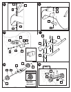
10. Insert bolt (21) through lower pivot bracket (22) as shown, bolt (21) will be
secured during step 12. Carefully place base assembly on its side. Install
lower pivot bracket (22) with bolt (23), washers (20) and lock nut (8) as
shown.
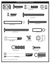
11. Secure both hinge tubes (24) to second wheel bracket (25) with carriage
bolts (26) and flange nuts (15).
12. Install wheels (27) onto axle (28) and wheel bracket (25) with push caps
(29) as shown.
13. Position base as shown. Secure wheel bracket assembly with disc (30),
washer (20) and nut (8) as shown. NOTE: Two people recommended for
this step.
14. Carefully reposition entire assembly as shown. IMPORTANT! Two people
recommended for this step.
15. Snap tinnerman nut (31) onto inner channel (32). Place inner channel into
outer channel (33) as shown.
16. Slide handle (34) into position as shown and secure with bolts (35),
washers (11), and nuts (15). Tighten completely.
17. Install bolt (36), washers (11), and nut (37) as shown. Tighten until
washers (11) are no longer loose. NOTE: Do not over tighten. Assemble
trigger (38) to handle assembly (34, 32, 31) as shown and secure with bolt
(39) and washer (11). Tighten completely.
18. WARNING: USE EYE PROTECTION WHEN INSTALLING SPRINGS.
Install trigger return spring (40) to handle assembly (32, 33) as shown.
19. Attach Accuheight label (41) to inner channel (32).
20. Attach spring (44) to pins (43) and install pins (43) onto pole mount bracket
(45). Attach other spring (44) to opposite side. NOTE: Gently enlarge
eyelets of spring with pliers if springs do not fit over pins.
WARNING: USE EYE PROTECTION WHEN INSTALLING SPRINGS.
21. Install pole mount assembly and reinforcement bracket (47) with carriage
bolts (46) to pole as shown. Tighten flange nuts (15) completely.
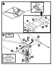
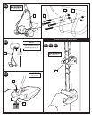
22. Push back sliding pin (43) as shown in Figure A to fit adjustable system
assembly through pole mount assembly. Then attach spring covers (48 &
49) onto pole mount bracket (45) with bolt (50), and nut (15) as shown in
Figure B.
23. Attach backboard support brackets (52) to the backboard frame using bolts
(53), spacers (51), and nuts (37) as shown.
24. Attach lower elevator tubes (56) and spring (68) to backboard support
brackets (52) using spacers (59), bolt (57), and nut (58) as shown. NOTE:
Rim mounting nuts and bolts (60) supplied with rim hardware.
25. Attach upper elevator tubes (63) to backboard support brackets (52) using
spacers (59), bolt (57), and nut (58) as shown.
26. Support pole on sawhorse. Attach backboard assembly to top pole section
(1) as shown. Then install pole cap (64). NOTE: Two people are
recommended for this step. Use caution; elevator assembly is heavy.
27. Install upper elevator tubes (63) to triangle plates (66) as shown.
Install handle assembly to lower elevator tubes (56) using bolt (57),
spacers (67), and nut (58) as shown. NOTE: Tighten bolt (57) in lock nut
(58) until flush (even) with lock nut’s outer edge. NOTE: Before going on
to next step, set adjustable system assembly to the 10’ (3.05 m) setting.
28. WARNING: USE EYE PROTECTION WHEN INSTALLING SPRINGS.
Insert bolt (57) through left side upper elevator tube (63), then stretch
springs (68) onto bolt (57). Insert bolt (57) through right side upper
elevator tube (63) and secure with nut (58).
29. Attach front cover (54) to hinge tubes (24) using carriage bolt (42) and
flange
nuts (15) as shown.
30. WARNING: DO NOT LEAVE ASSEMBLY UNATTENDED WHEN
EMPTY, MAY TIP OVER.
Apply height and moving label (76) to front of pole as shown.
31. Roll completed assembly to desired playing area. Secure assembly to
ground using strap (61) and tie down stake (7). Fill tank with 34 gallons of
water. IMPORTANT! Add two gallons (7.6 Liters) of non-toxic
antifreeze in sub-freezing climates. Add two gallons (7.6 liters) to tank
to prevent freezing in sub-freezing climates. Snap cap (62) into place.
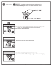
WARNING: DO NOT ALLOW CHILDREN TO ADJUST HEIGHT.
32. Grasp handle and depress lever.
33. Push toward pole while holding lever. Raise or lower lever to desired
height while pushing forward on handle.
34. Release handle making sure that horizontal pin (43) is locked into slot.
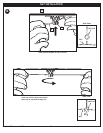
WARNING: USE OF THIS PRODUCT WITHOUT PROPER
INSTALLATION OF SMART CLIPS, OR WHEN ALL SMART CLIPS ARE
NOT PRESENT COULD RESULT IN BODILY HARM. BE SURE TO
FOLLOW DIRECTIONS CAREFULLY.
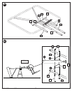
35. Install net clips as shown. (See illustration)
36. Install net as shown. (See illustration)
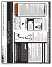
BEFORE YOU START!
To ensure optimal playability of backboard system, a close tolerance fit between the elevator components and
hardware is required. Test fit large bolts into large holes of elevator tubes, backboard brackets and triangle plates.
Carefully rock them in a circular motion to ream out any excess paint from holes if necessary.