


4
P/N 211955C 04/03
INSTRUCTIONS
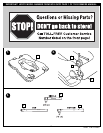
IMPORTANT! WRITE MODEL NUMBER FROM BOX ONTO PAGE 1 OF
THIS OWNERS MANUAL
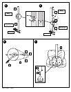
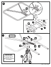
1. Remove all contents from underside of tank. Keep tank (1) bottom side
up.
2. Insert axle rod (2) through wheel (3), as shown. Secure wheel assembly
to tank (1) by tapping wheel downward with hammer, snapping it into
position. Repeat for opposite side, then carefully, turn tank (1) over.
3. Mark pole sections with tape as shown.
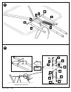
4. IMPORTANT! Center alignment slot of middle pole section (5) in a
lower hole of top pole section (4) as shown. While maintaining
alignment, bounce pole top (4) and middle section (5) together as shown
until they no longer move toward taped reference mark. Upright
assembly. NOTE: Pole sections should have a
3-1/2” (9 cm) overlap minimum.
5. IMPORTANT! Center alignment slot of lower pole section (6) in a
lower hole of middle pole section (5) as in step 4. While maintaining
alignment, bounce assembly and lower section (6) together as shown
until they no longer move toward taped reference mark. NOTE: Pole
sections should have a
3-1/2” (9 cm) overlap minimum.
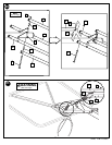
6. Install rod (7) through holes in bottom pole section (6) and eyebolt (8).
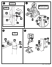
7. Insert pole assembly into tank assembly as shown.
8. Carefully place unit on its side. Secure pole bottom (6) to tank with
anchor strap (52), washers (9 & 13) and nut (10) as shown. Upright unit.
NOTE: Keep unnecessary pressure off of the pole assembly when in this
position. Two people recommended for this procedure. IMPORTANT!
DO NOT over tighten.
9. Secure strut tubes (11) to bottom pole section (6) as shown.
WARNING: TIGHTEN BOLT (14) IN LOCK NUT (12) UNTIL FLUSH
(EVEN) WITH LOCK NUT’S OUTER EDGE.
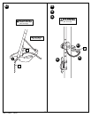
10. Carefully place unit in the side position and secure strut (11) to tank (1)
as shown. Completely tighten. Repeat for opposite side. NOTE: Keep
unnecessary pressure off of the pole assembly when in this position.
Two people recommended for this procedure.
11. Install pole mount bracket (17) and reinforcement bracket (37) with
carriage bolts (18) as shown. Tighten flange nuts (16) completely.
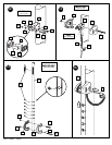
12. Attach spacers (22, 23) to pole mount bracket (17) with bolts (21),
washers (19), and nuts (20) as shown. IMPORTANT! Tighten just until
washers (19) stop moving.
13. Attach covers (24) onto pole mount bracket (17) with carriage bolt (25)
and nut (16) as shown. IMPORTANT: Loop end of pin lanyard (27)
over carriage bolt (25) during this assembly. NOTE: Assemble
lanyard (27) to locking pin (26) as shown.
14. Apply logo and height indicator labels (29) to adjustment rod (28) as
shown. Attach handle parts (32, 33) to adjustment rod with screw (31),
carriage bolt (30), and flange nut (16) as shown. IMPORTANT!
Indicator labels should be applied as close to holes as possible to
prevent labels from being damaged during height adjustment.
15. Insert handle assembly through pole mount assembly as shown. Lock
pole assembly in place at the 10’ (3.05 m) mark with pin (26).
16. Attach backboard support brackets (34) to the backboard frame using
bolts (21), spacers (36), and nuts (20) as shown.
17. Assemble lower elevator tubes (40) as shown. NOTE: Test fit bolts into
holes of brackets (34) and carefully rock them in a circular motion to
ream out paint from holes if necessary. IMPORTANT! It is necessary
for all parts to be installed for this mechanism to work safely and
properly.
18. Assemble upper elevator tubes (43) to backboard brackets (34).
19. Support pole on sawhorse. Attach backboard assembly to top pole
section (4) as shown. Install pole cap (46). NOTE: Two people are
recommended for this step. Use caution; elevator assembly is heavy.
20. Install upper elevator tubes (43) to triangle plates (45) as shown. Install
handle assembly to lower elevator tubes (40) using bolt (47), spacers
(44), and nut (39) as shown. NOTE: Before going on to next step, set
adjustable system assembly to the 10’ (3.05 m) setting.
21. Insert bolt (47) through left side upper elevator tube (43), then stretch
spring (41) onto bolt (47). Insert bolt (47) through right side upper
elevator tube (43) and secure with nut (39).
WARNING: USE EYE PROTECTION WHEN INSTALLING SPRINGS.
22. Roll completed assembly to desired position. Secure assembly to ground
using anchor strap (52) and tie down stake (53). Fill tank with water
(approx. 30 gallons (115 Liters)) or sand (approx. 255 lbs. (113 kg)) and
snap cap (49) in place. IMPORTANT! Add two gallons (7.6 Liters) of
non-toxic antifreeze in sub-freezing climates.
WARNING: DO NOT LEAVE ASSEMBLY UNATTENDED WHEN
EMPTY, MAY TIP OVER.
23. While holding handle, remove pin (26).
WARNING: DO NOT ALLOW CHILDREN TO ADJUST HEIGHT.
24. Move elevator up or down to desired height.
25. Replace pin (26) full length to lock system at desired height.
26. Apply height and transport label (54) to front of pole as shown.
27. Install front cover (35) onto struts (11) as shown.
28. Loop zip tie (56) around strut (11) and cover (35). Pull flat end of zip tie
(56) through square end of zip tie until completely tightened. NOTE:
Ridges on zip tie (56) should be on inside of loop when pulling flat end of
tie through square end.
29. Once fully secured in the four areas shown, trim excess of zip tie (56)
with scissors.
WARNING: USE OF THIS PRODUCT WITHOUT PROPER
INSTALLATION OF SMART CLIPS, OR WHEN ALL SMART CLIPS
ARE NOT PRESENT COULD RESULT IN BODILY HARM. BE SURE
TO FOLLOW DIRECTIONS CAREFULLY.
30. Install net clips as shown. (See illustration)
31. Install net as shown. (See illustration)
WARNING: IF YOUR SYSTEM IS EQUIPPED WITH
AN ACRYLIC BACKBOARD, EXAMINE
BACKBOARD FOR ANY DAMAGE THAT MAY
HAVE OCCURRED DURING SHIPMENT. CRACKS
IN THE BACKBOARD COULD RESULT IN SUDDEN
BREAKAGE. IF BACKBOARD IS DAMAGED IN
ANY WAY PRIOR TO OR AFTER ASSEMBLY, CALL
TOLL-FREE NUMBER FOR FREE REPLACEMENT:
U.S. 1-800-558-5234; CANADA: 1-800-284-8339;
http://www.huffysports.com
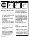
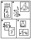
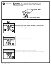
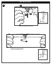
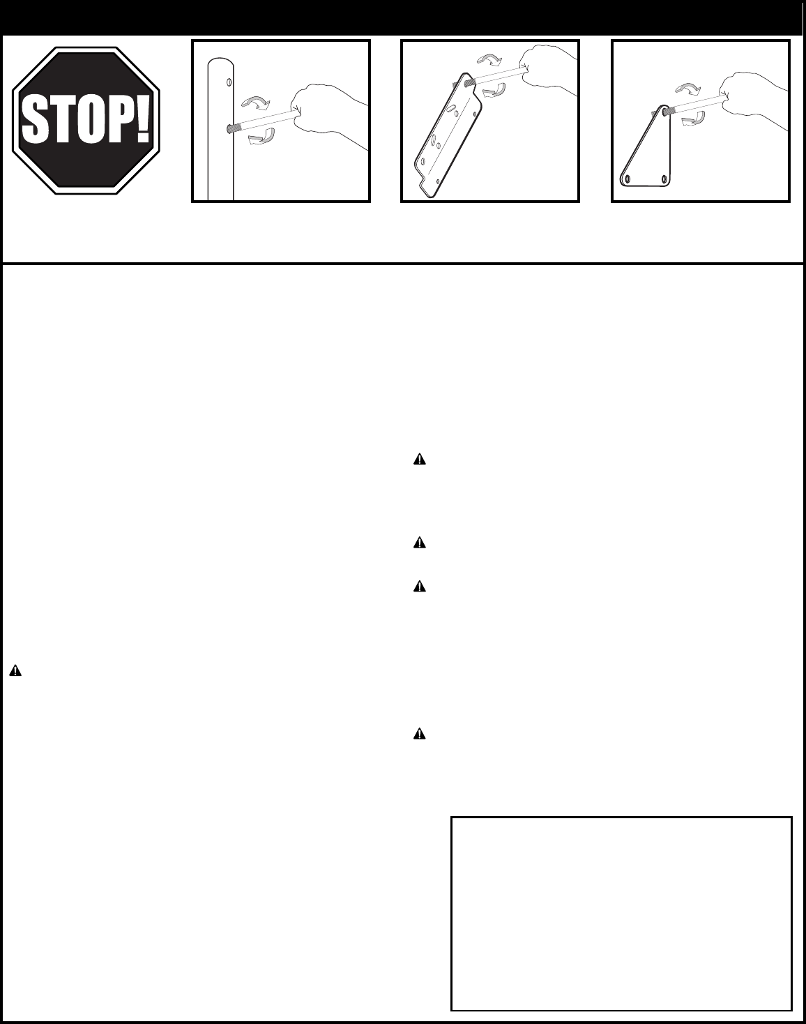
BEFORE YOU START!
To ensure optimal playability of backboard system, a close tolerance fit between the elevator components and hardware is required. Test fit
large bolts into large holes of elevator tubes, backboard brackets and triangle plates. Carefully rock them in a circular motion to ream out any
excess paint from holes if necessary.