


ASSEMBLY
INSTRUCTIONS
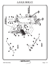
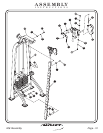
FRAME ASSEMBLY
Step 2c
FITNESS SYSTEMS
R
HOIST
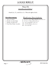
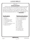
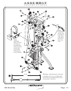
1 - Frame Assembly
9 - Guide Rod
10 - Weight Bumper
11 - 20 LB. Intermediate Weight
12 - 8.6 LB Aluminum Weight
13 - Center RH (BRK) Assembly
14 - Add on Rod
15 - Cable Pulley Weight Mount Assembly
16-5LBCast Add on Weight
17 - Weight Selector Pin
Part Descriptions
C - 3/8”-16 x 3 1/2” Button Head Screw
D - 5/16”-18 x 1” Button Head Screw
E - 3/8”-16 x 1” Button Head Screw
F - 3/8”-16 x 1” Button Head Screw
AC - 3/8” Split Washer
AD - 3/8” Flat Washer
AE - 5/16” Lock Washer
AF - 5/16” Flat Washer
AG - 3/8” Flat Washer
AH - 3/8” Lock Washer
AJ - 3/8” Lock Washer
AK - 5/8” Nylon Washer
BB - Serrated Hex Nut
CA - Guide Bearing (Short)
CB - Guide Bearing (Tall)
CC - Selector Pin Lanyard
Hardware Descriptions
2061Assembly
Page 9
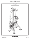
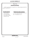
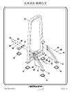
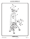
In this step, start by pressing (CB) and (CA) into (12), insuring (CB)
is pressed in the same side as (14) is mounted to (13). Place (9) over the
two holes in the bottom of (1). Now slide (9) into the holes. Slide (11)
and (12) onto (9). Make sure (12), (11), and (9) are sitting level, then
fasten the top of each (9) to (1). Next attach (14) to (13). Secure (13) to
(12), slide on (16) and attach another (14) to (1). Attach bigger end of the
(CC) to (13), and the other end to (17). Then bolts.Wrench tighten