


6
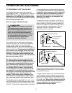
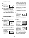
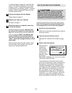
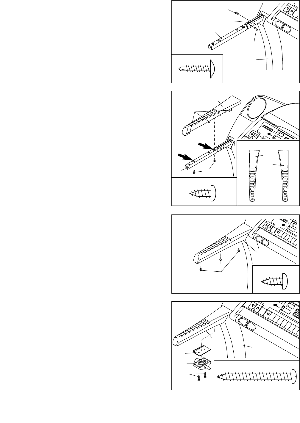
6. Orient the Latch Spacer (106) and the Latch Assembly
(32) as shown. Attach the Latch Spacer and the Latch
Assembly to the Left Bottom Handgrip (82) with the 1 3/4”
Screws (105) as shown. Tighten the two Screws as
tightly as possible.
32
82
105
106
64
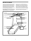
7. Make sure that all parts are properly tightened before you use the treadmill. Keep the included allen
wrench in a secure place; the allen wrench is used to adjust the walking belt (see page 24). To protect the
floor or carpet from damage, place a mat under the treadmill.
105
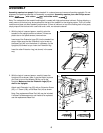
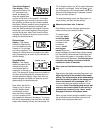
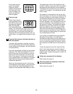
3. Orient one of the Handgrip Extensions (34) as shown and
insert it as far as possible into the post on the left Upright
(64). If necessary, tap the Handgrip Extension with a rub-
ber mallet to fully insert it. Attach the Handgrip Extension
with two 3/4” Tek Screws (35), one towards the front of
the post and the other towards the back.
Attach the other Handgrip Extension to the post on the
right Upright (not shown) in the same way.
34
35
35
64
Post
3
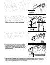
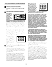
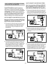
4. See the inset drawing. Identify the Left Top Handgrip
(31); there are identifying marks inside of the Handgrips.
Set the Left Top Handgrip on the left Handgrip Extension
(34). Insert two 1/2” Screws (33) into the two holes in
the Handgrip Extension indicated by the arrows.
Tighten the Screws into the Left Top Handgrip.
Important: Do not tighten the Screws into the plastic
bosses on the bottom of the Left Top Handgrip.
31
Bosses
33
34
4
31
43
5
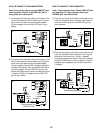
5. Attach the matching Left Bottom Handgrip (82) with three
1/2” Screws (33).
Attach the Right Top Handgrip and the Right Bottom
Handgrip (not shown) as described above.
33
33
33
35
7
82