


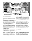
5. Make sure that all parts are properly tightened before
you use the treadmill. Place a mat beneath the tread-
mill to protect the floor. For your benefit, familiarize
yourself with the information on pages 25 and 26.
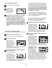
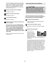
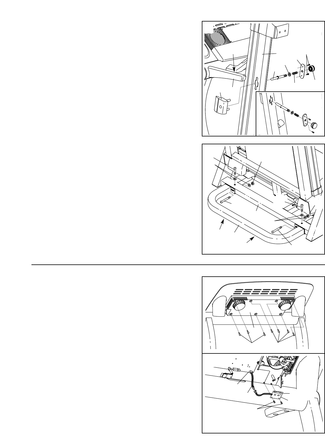
4. Put the treadmill in the storage position (see HOW TO
FOLD THE TREADMILL FOR STORAGE on page 23).
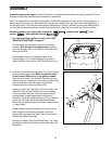
Have a second person hold the treadmill in the upright posi-
tion. Place the U-base (20) against the base of the Uprights
(65) as shown. Make sure that the U-base is turned so the
Bumpers (98) are on the bottom. Finger tighten two 2”
Bolts (26) and Base Washers (129) into the base of the
Uprights and the U-base. Attach the U-base with two 3” Bolts
(23), Base Washers and U-base Nuts (51) as shown. Tip the
treadmill forward if necessary. Tighten the two 2” Bolts.
51
23
20
98
98
65
4
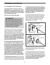
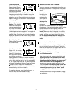
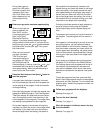
If you purchase the optional chest pulse sensor (see page
22), follow the steps below to install the receiver and the
short jumper wire included with the chest pulse sensor.
1. Make sure that the power cord is unplugged. Remove the
indicated 3/4” Screws (40) from the Console Back (117).
Remove the Console Back.
2. Connect the Short Jumper Wire (A) to the wire on the
Receiver (B). Connect the other end of the Short Jumper
Wire to the PULSE jack on the back of the Console (80).
Turn the Receiver (B) so the cylinder is on the side
shown, and hold the Receiver against the back of the
Console (80). Attach the Receiver with the two Small
Screws (C) included with the receiver.
Make sure that no wires are pinched. See step 1.
Reattach the Console Back (117) with the 3/4” Screws (40).
You may discard the other wires included with the receiver.
40
C
117
80
A
B
40
1
51
26
Cylinder
2
7
55
69
5
70
3
72
68
62
10
Hole
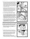
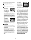
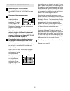
3. (Note: The parts shown in this step may be preassembled.)
With the help of a second person, raise the Frame (55) and
hold it. Insert the Left Frame Guide (68) into the left side of
the Frame. Remove the Lock Knob (67) from the Lock Pin
(72). Make sure that the Lock Pin Collar (70) and the Spring
(69) are on the Lock Pin. Insert the Lock Pin into the Frame
and the Left Frame Guide. Press the Latch Insert (5) onto
the Frame, with the Lock Pin in the center hole. Tighten the
Lock Knob onto the Lock Pin.
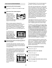
Align the Lock Pin (72) with the hole in the Left Foam Grip
(62) by sliding the Left Frame Guide (68) up or down.
Make sure that the Lock Pin can be inserted fully into the
hole. Hold the Left Frame Guide in place as you tighten
two 1/2” Screws (10) into the Latch Insert and the Left
Frame Guide. Note: It may be necessary to pull the Lock
Knob (67) to access and tighten the Screws.
67
129
129
23
26