


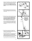
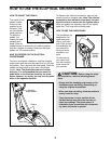
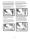
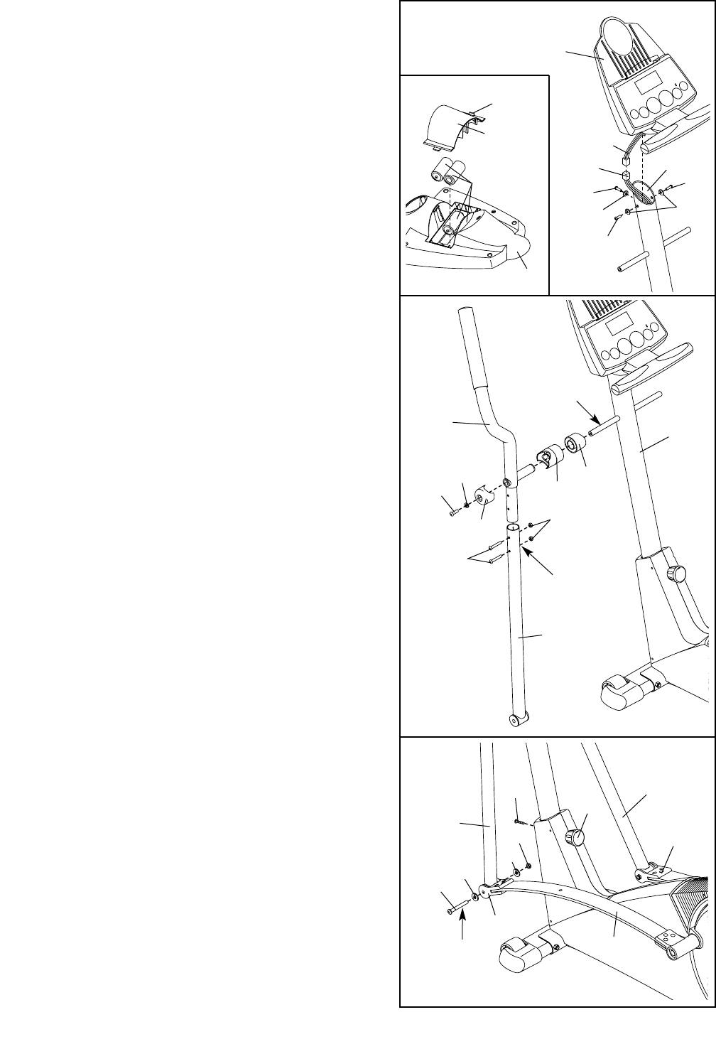
7. Hold the lower end of the left Handlebar Leg (79) inside
of the left Front Flex Bracket (17). Apply grease to an
M10 x 78mm Button Bolt (27). Attach the left Handlebar
Leg to the left Front Flex Bracket with the Button Bolt,
two M10 Washers (38), and an M10 Nylon Locknut
(29). Do not overtighten the Nylon Locknut; the left
Handlebar Leg must be able to pivot freely.
Attach the right Handlebar Leg (79) to the right Front
Flex Bracket (17) in the same way.
Tighten the M6 x 25mm Screw (63) into the Upright (2).
Turn the Upright Knob (91) clockwise until it is tight.
Refer to step 6. Tighten the M8 x 45mm Button Bolts
(83) in the Handlebar Legs (79).
17
17
14
27
38
38
29
Grease
7
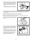
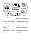
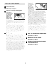
5. The Console (5) requires four “D” batteries (not includ-
ed); alkaline batteries are recommended. Refer to the
inset drawing. Press the tab on the battery cover, and
lift off the battery cover. Insert four batteries into the
battery compartment. Make sure that the batteries
are oriented as shown by the diagram inside the
battery compartment. Reattach the battery cover.
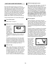
While another person holds the Console (5) in the
position shown, connect the wire harness on the
Console to the Upper Wire Harness (86). Insert the
excess wire harness into the Upright (2). Next, attach
the Console to the Upright with three M10 x 27mm
Screws (71) and three M10 Split Washers (70). Be
careful to avoid pinching the wire harnesses.
5
86
71
71
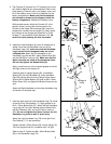
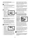
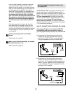
6. Identify the Left Handlebar (9), which is marked with a
sticker. Insert the Left Handlebar into one of the
Handlebar Legs (79); make sure that the Handlebar
Leg is turned so the hexagonal holes are on the
indicated side. Attach the Left Handlebar to the
Handlebar Leg with two M8 x 45mm Button Bolts (83)
and two M8 Nylon Locknuts (46). Make sure that the
Nylon Locknuts are inside of the hexagonal holes.
Do not fully tighten the Button Bolts yet.
Apply a small amount of the included grease to the left
and right axles on the Upright (2).
Carefully slide an Upright Spacer (26), a Handlebar
Spacer (25), the Left Handlebar (9), and a Handlebar
Cap (23) onto the left axle on the Upright (2) as shown.
Slide an M10.3 Black Washer (53) onto an M8 x 19mm
Button Screw (22), and tighten the Button Screw into the
axle.
Attach the Right Handlebar and the other Handlebar Leg
(not shown) in the same way.
Grease
6
7
2
Wire
Harness
70
70
71
26
25
9
2
23
22
53
83
46
Hexagonal
Holes
79
63
91
79
79
5
Tab
Batteries
Battery
Cover
5